20 – CV Switching

Learn how to switch between 2 CV sources that control a single destination. This method can expand the number of patterns you use in a Matrix (from 32 to 64) to control a single destination. It can also allow you to switch between two RPG-8 Arp devices or any two CV sources anywhere in Reason and Record for that matter.

At some point when working with CV, you end up wondering if you can expand beyond the limits. For example, if you have a Matrix loaded with 32 pattern banks, you’re going to wonder if you can push it to 64. If you have an Arp applied to an instrument, you’re going to wonder if you can have two Arps applied to the same instrument. I know that’s what I was wondering a few nights ago. And that’s the subject of this article. How to expand upon CV connections by switching between these CV devices in real-time.

You can download the project files in the following zip file: cv-switching. These project files include 2 Combinators that show you how to switch between two matrixes or two Arps on the fly. Both Combinators are connected to the same mixer, so to hear each one separately, just mute/solo each one and press play on the Transport bar.

Switching between 2 Matrixes

  1. First open up a new document, and first place a 14-2 Mixer at the top (if you are in Record, you won’t need the mixer, because everything gets tied to your BIG mixer).
  2. Now, open up a Combinator and holding Shift down, place a sound source at the top (for example, a Subtractor), a Thor underneath that, and then two Matrixes underneath the Thor.
  3. Next, flip the rack around and let’s route the audio up.  Route the Left Audio output from the Combinator to Channel 1 on the mixer. Then Route the Audio out of the Subtractor to the Left audio In of the Combinator (From Devices).
  4. Now for the CV routings. Route the CV 1 and CV 2 Modulation outputs from the Thor to the Gate and CV Sequencer Control section of the Subtractor, respectively. Take the Note and Gate CV of Matrix “A” and route them to the CV 1 and CV 2 Modulation inputs of the Thor, respectively. Finally, route the Note and Gate CV of Matrix “B” to the CV 3 and CV 4 Modulation inputs of the Thor, respectively.
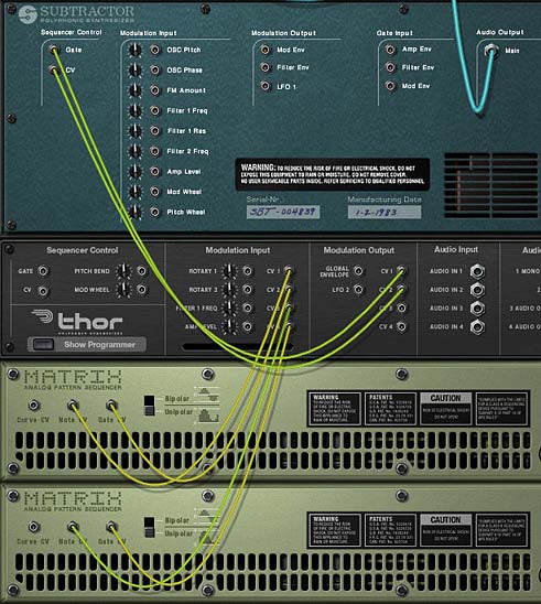
    Proper CV routings for the Thor and Matrix A & B devices
    Proper CV routings for the Thor and Matrix A & B devices
  5. Flip the rack around. On the Subtractor, select a patch you like, or program in some patch parameters that you want to hear. Alternately, leave the default init patch as it is.
  6. On the Thor, completely initialize the patch by turning Oscillator 1 Off, Bypassing Filter 1, turning off the Mod/Filter/Amp/Global envelopes, and reducing the Range, Polyphony, and Release Polyphony down to zero (0) in the Global section. We’re using Thor purely as a CV switcher between the two Matrixes.
  7. In the Modulation Matrix area of Thor, enter the following:

    CV In1 : 0 > CV Out 1

    CV In2 : 0 > CV Out 2

    CV In3 : 0 > CV Out 1

    CV In4 : 0 > CV Out 2
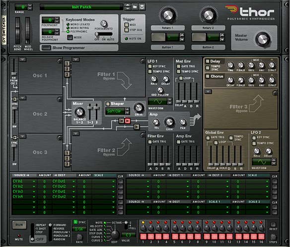
    A completely initialized thor, with the proper routings in the Modulation Bus Routing Section (MBRS)
    A completely initialized thor, with the proper routings in the Modulation Bus Routing Section (MBRS)
  8. In the Matrix A, fill up all 32 of your pattern banks with random patterns or midi patterns that you want to use to play the Subtractor. Random patterns are just quicker for the purposes of this exercise.
  9. In the Matrix B, do the same. However, note that in the example file I have not loaded any patterns into Matrix B. This is so that you can hear the difference when you swtich between Matrix A and Matrix B. But for practical purposes you’ll want to load up all 32 pattern banks with more patterns with which to play the Subtractor sound source.
  10. In the Combinator’s Programmer, select the Thor device (I call it the CV Switcher) and enter the following settings for the Modulation Routing:

    Button 1 > Mod 1 Dest Amount : 100 / 0

    Button 1 > Mod 2 Dest Amount : 100 / 0

    Button 1 > Mod 3 Dest Amount : 0 / 100

    Button 1 > Mod 4 Dest Amount : 0 / 100
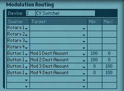
    The Combinator's Modulation Routings for the Thor device (CV Switcher)
    The Combinator's Modulation Routings for the Thor device (CV Switcher)
  11. For the Matrix A and Matrix B devices, enter the following programmer modulation (for both Matrixes):

    Rotary 1 > Pattern Select : 0 / 31

Now, when you press the play button on the Transport, both matrixes will engage, but only one will be used to play the Subtractor, depending on the on/off state of the first button on the Combinator. This first button determines which Matrix is used (if off, Matrix A is used. If on, Matrix B is used). The first Rotary on the Combinator moves through all 32 pattern banks of both Matrixes, thus allowing you access to 64 pattern banks to apply to your Subtractor sound source.

Everything gets switched using the Thor. And the beauty of this type of setup is that you don’t need to worry about Matrix delay problems. Since both Matrixes are always running, and the Thor is used to switch between them, the switching is done completely in real-time with no latency whatsoever.

Ramping it up with an Arp

I won’t go into too much detail about applying this same technique to an Arp. You have the sample file, and you can open this up and see how it’s done. But basically, instead of two Matrixes, you have two Arps that are going through two Thors (one Thor controls the Note / Gate CVs, and the other Thor controls the Pitch/Mod wheel CVs).

One other difference is that you will need a separate Matrix to play the Combinator (ie: the Matrix Note / Gate CV will be sent to the Combinator’s Sequencer Control). This is to ensure something is triggering your sound source, whereas in the previous Matrix example, the matrix units themselves were triggering the sound source.

Alternately, if you don’t want to trigger your sound source via the Matrix, you can set up two sequencer tracks (one for each Arp device) and add your midi note clips there. If you want to switch between both Arps and have them both playing the same part exactly, just duplicate the note clips on both Arp tracks so they are identical. Or have some fun switching up the notes. Experiment with this one.
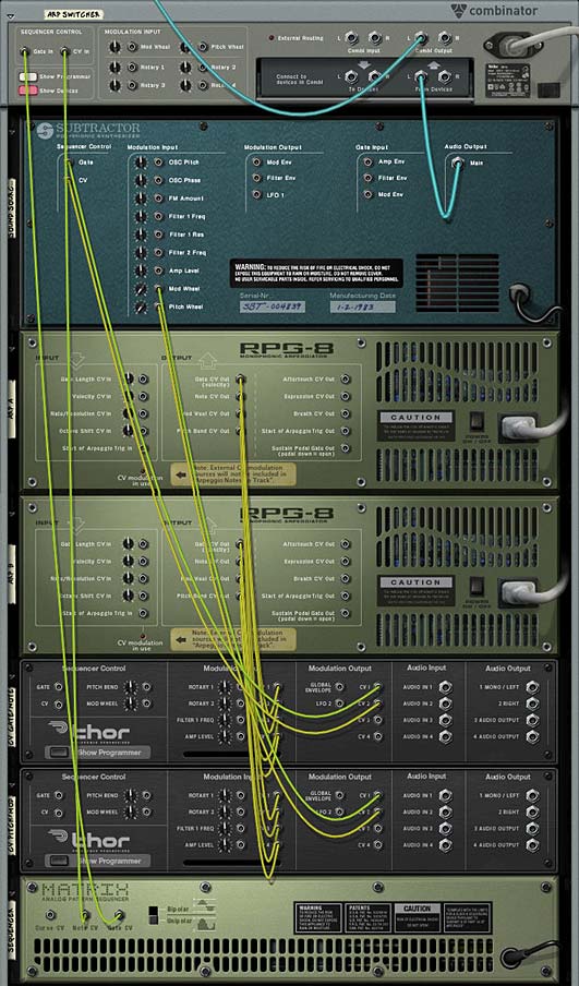
Proper routings on the back of the rack for the Arp Switcher Combinator

Where do I go from here?

Using this method you can switch between any two CV sources going to the same destination CV input. So let your mind wander and try it out using a Scream or RV7000 or any filter envelope. Anywhere you use CV, this method hopefully inspires you to try playing around with CV and using it more creatively when working on your songs.

Did you find this tutorial useful or beneficial? Let me know. And as always, if you have other ideas related to CV switching, please share them with all of us.

Arp Box

This is an Arp Box Combinator I developed for Lewis from “Resonant Filter,” which uses 2 Arps working together to provide some interesting sound design potential. The Combinator is fully programmed and you can switch out the sound sources if you like.

Download the Combinator: arp-box


Description: Lewis from “Resonant Filter” told me he really liked Arps, so I thought I would put another one together which focusses solely on utilizing the Arp within a Combinator, and providing for most of the control of the Arps from the Combinator. So this is an Arp Box Combinator I developed, which uses 2 Arps working together to provide some interesting sound design potential. The Combinator has full automation applied to the Rotaries and Buttons. Furthermore, it uses the Malstrom Curves to adjust some settings on the Arps (documented below).

Features: The “Arp Box” has several features associated with it. I was attempting to get a cross between a playful glitch-inspired machine and a traditional Arp. The following are the main features according to Combinator assignments:

Pitch Bend: This affects the Modulation Rate of both the Rate and Gate for the 2 Arps. Moving it down slows down the arp, while moving it up can speed up the Arp, and create a fast-pitch stuttering effect. Best used when performing for quick little quirky Arp changes.

Mod Wheel: This affects the mode of the Arps at the same time. Moving the Mod wheel changes the Arps’ progressions (either Up / Up+Down/ Down, etc.)

Rotary 1: Controls the Rate/Gate Malstrom’s A curve, which in turn affects the Rate of both Arps. Adjusting this Rotary cycles through the Malstrom’s 31 curves.

Rotary 2: Controls the Rate/Gate Malstrom’s B curve, which in turn affects the Gate Length of both Arps. Adjusting this Rotary cycles through the Malstrom’s 31 curves.

Rotary 3: Controls the Velocity Malstrom’s A curve, which in turn affects the Velocity of both Arps. Adjusting this Rotary cycles through the Malstrom’s 31 curves.

Rotary 4: Adjust’s the Thor’s Filter 3 Frequency.

Button 1: This turns the Arps’ Hold buttons on (when lit) and keeps Hold off (when not lit).

Button 2: Affects the Insert of the Arps. When the button is not lit, the Insert is 3-1. When the button is lit, the Insert is 4-2.

Button 3: When this button is off, the Arps do not respond to velocity shifting from the Velocity Malstrom. Velocity is constant. When turned on, the Velocity is shifted according to the curve in the Velocity Malstrom. Note that with the Velocity turned off, adjusting Rotary 3 has no effect.

Button 4: When this button is off, there is very little resonance applied to the Thor Filter (and as a result, the sound). When this button is turned on, a high resonance is applied to the Filter. There’s also a little more balancing going on in order to more closely match the volume between low and high resonance, but essentially this is a quick way to get a whole new sound out of the Arp Box.

Note: In addition to the above programming, you can use the Thor Filter underneath the 6:2 Line Mixer to set up the Delay and Chorus for some quick FX. Button 1 turns on the Delay, and Rotary 1 adjusts the Delay Time. Button 2 turns on the Chorus, and Rotary 2 adjusts the Chorus Delay. So you have a few additional parameters with which to work.

Usage: It can be used as is to insert an adjustable Arp in your tracks, played in a live performance setting, or used as a template with your own sounds. Just keep the Arps as they are and switch out the sound source to your own device or patch.

Other Notes: Feel free to change the Patches for the two NN-XTs or change the device to another sound source (either a Sampler or Synth). Also, you don’t have to have both devices playing the same sound at all. So experiment here first. Also, by default (and for the default sound of the Arp Box), the first arp is set to -1 Octave Shift, and the second Arp is set to -2 Octave Shift. This is so that the first Arp provides the main melody line, while the second Arp provides a bottom end. Depending on your sound, you may want to adjust this Octave Shift setting to whatever you wish. Also, if you don’t like the Low Pass Ladder filter in Thor, you can switch it to any other filter. Depending on your sound source, one of the other filters may suit your own patch better. Finally, if the Rate of the Arp is not to your liking, you’ll have to change this setting on one or both Arps manually. Though the Pitch Bend wheel affects the Rate, it may not be the best rate when the Pitch Bend is in its default position. Playing with the Rates on both Arps can produce some interesting sound designs.

Let me know what you think?

6 – Vocoder Arp Machine

A very flexible Combinator mashup that plays an Arped up Thor run through a Vocoder. A second Thor is used to modulate the sound. Use this Combinator as a template to drop in your own Thor patches and then take it out for a spin at your next live gig. All the Combinator parameters are assigned to toy with the Arp / Vocoder settings. After all, the more flexible the Combinator is, the more use you will get out of it.

I was looking through eXode’s fabulous collection of free patches and combinators in his massive synthesis refill (available from the Propshop’s Free Refill Download Page – A must have for anyone who is looking for a great collection of new sounds!) when I came across a few patches that were hidden away with (arp) in parentheses after the patch names. Being one who loves a good arp sound I started to delve a little deeper into how it was put together. So this became the inspiration for this project. It fuses an arp with two thors — one for the modulation and another as the carrier, and both Thors feed through a Vocoder to the final output.

Now taking things a few steps further, I decided to deviate from what eXode did and add on a few modifications. Firstly, the sounds I used were completely my own (I didn’t want to copy eXode’s brilliant work). And I then took things another step further by assigning parameters to the Combinator rotaries and buttons. This way, you can use the Combi as a performance tool as well. And you can experiment with your own Thor sounds for the carrier and change the way the vocoder operates by toying with the Thor synth parameters, creating your own endless variety of Arp Vocoder machines.

So this is a bit of a mashup, being a Combinator that plays just fine as it is, or used as a template where you can drop in your own Thor patches. Finally, it can be used in live performance, since all the Combinator parameters are assigned for this purpose. After all, the more flexible the Combinator is, the more use you will get out of it.

The project files can be downloaded here: vocoder-arp. It contains an .rns file with a single Combinator which is pre-programmed to most of the major parameters you’ll need to adjust the Filter Frequency, Arp and Vocoder parameters.

Setting up the Vocoder Arp Template.

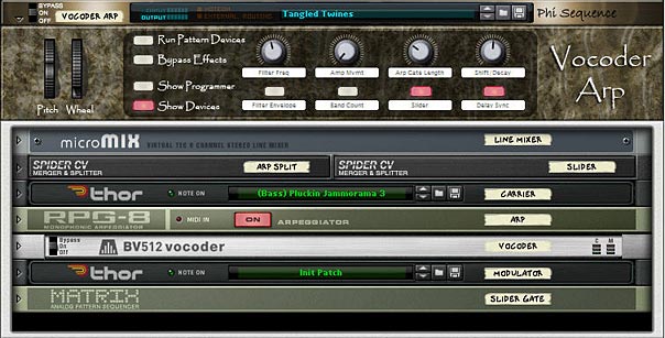
  1. First, create a Combinator, then inside the combinator create a 6:2 Line Mixer, Thor, RPG-8 Arpeggiator, BV512 Vocoder, and then holding Shift down (to disable auto routing), create another Thor. Flip the rack around and route the bottom-most Thor’s 1 Mono / Left Output to the Modulation input on the Vocoder. This is the basic setup for the arped-up vocoder. The first Thor in the Combi is the carrier, and an Arp is tied to this Thor. In other words, this is the main sound going into the Vocoder. The second Thor in the Combi is used to Modulate that Carrier sound through the Vocoder.
  2. Next, holding Shift down, create two Spider CV Merger/Spliters below the Combinator’s Line Mixer. Then hold Shift down and create a Matrix at the bottom of the stack. Set the steps to 4 and the resolution to 1/4th. Switch the Matrix mode to Curve, flip the rack around to the back and switch the curve mode to Bipolar. Then flip the rack around again and set up a curve pattern so that step 1 and 3 are +64 and step 2 and 4 are -64.
  3. The front of the Vocoder Arp with all devices
    The front of the Vocoder Arp with all devices
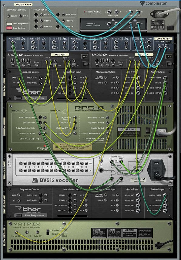
  4. Flip the rack around and on the first Spider connect the Arp Note CV out to Split A in and the Arp Gate CV out to Split B in. Connect one of the splits from Split A to the Carrier Thor’s CV in. Then connect the inverted split from Split A to the  Carrier Thor’s CV1 Modulation input. Connect one of the splits from Split B to the Carrier Thor’s Gate input, and another split from Split B to the Carrier Thor’s CV2 Modulation input.
  5. On the second Spider connect the Curve CV output from the Matrix to Split A’s input. Then connect one of the splits from Split A to the Split B input on the same Spider. Connect another split from Split A to the Vocoder Hold input. Connect the third split from Split A to the Carrier Thor’s CV3 Modulation input. Then connect the inverted split from Split A to the Arp’s Velocity CV in. on the Spider’s Split B, connect the inverted split to the Arp’s Octave Shift CV in. That just about does it for the CV routings. Luckily you can see the Combinator for yourself when you download the project files, because that was a mouthful. But it sounds more complex than it actually is.
  6. Moving to the Arp, and while you’re on the back of the rack, remove the CV cables from the Mod Wheel and Pitch Bend CV out. This way when you use the Pitch Bend, it will only affect the Thor Carrier’s Pitch Bend setting. Now flip the rack around again. Set up the Arp with an Octave Range of 2, and Insert set to Low. On the Vocoder, set the Attack to 8.
  7. The back of the rack with all the routings in place
    The back of the rack with all the routings in place
  8. Now we move to the Combinator programming. Click the Show Programmer button and enter the following settings:

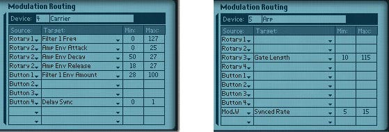
    For the Thor Carrier:

    Performance Controllers > uncheck the Mod Wheel

    Rotary 1 > Filter 1 Freq: 0 / 127

    Rotary 2 > Amp Env Attack: 0 / 25

    Rotary 2 > Amp Env Decay: 50 / 27

    Rotary 2 > Amp Env Release: 18 / 27

    Button 1 > Filter 1 Env Amount: 28 / 100

    Button 4 > Delay Sync: 0 / 1

    For the Arp:

    Rotary 3 > Gate Length: 10 / 115

    Mod.W > Synced Rate: 5 / 15

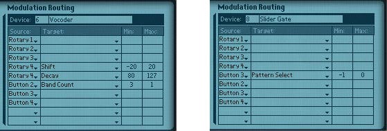
    For the Vocoder:

    Rotary 4 > Shift: -20 / 20

    Rotary 4 > Decay: 80 / 127

    Button 2 > Band Count: 3 / 1

    For the Thor Modulator:

    Performance Controllers > uncheck the Pitch Bend and Mod Wheel

    For the Matrix:

    Button 3 > Pattern Select: -1 / 0

  9. The Combi's mod programming for the Thor Carrier (left) and Arp (Right)
    The Combi's mod programming for the Thor Carrier (left) and Arp (Right)
    The Combi's mod programming for the Vocoder (left) and Matrix (right)
    The Combi's mod programming for the Vocoder (left) and Matrix (right)
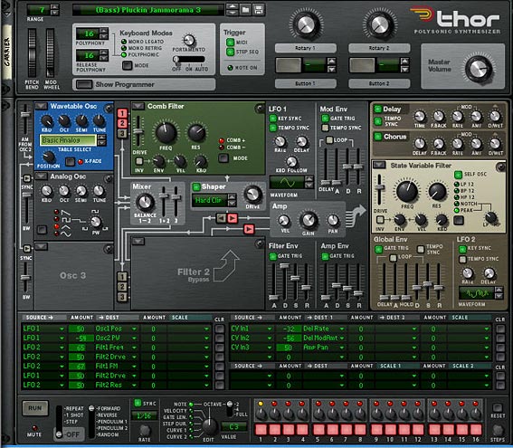
  10. Now flip the rack to the front now, and load up your favorite patch in the Thor carrier. Usually a bright lead will work best, but experiment with any sound you like. You can take a look at how I programmed the Thor in the image below. I won’t go into all the settings that were used. You can pretty much see them here. However, there are some core settings that are needed in the Modulation Bus Routing Section (MBRS) in order to have the Combinator function properly. On the right side of the Bus, create the following routings*:

    CV In1: -32 > Del Rate

    CV In2: -56 > Del ModAmt

    CV In3: 50 > Amp Pan

  11. The front of the Thor Carrier
    The front of the Thor Carrier
  12. Add a matrix below the Combinator so that it is playing the Combi. Then enter a pattern and hit play. This tests out the sounds of the Combi as you experiment with your Carrier and Modulator. For the modulator, you usually want something atonal or heavy on the noise. Unmusical is best. Droning is perfect to affect your carrier signal. This is the fun part where you toy with the Thor until you get something you like. The nice thing is that you have a wide variety of sounds to choose from using the Thor synth.

An explanation of the Combinator Programming

Pitch Bend: This affects only the Thor Carrier as you would expect a pitch bend to operate.

Mod Wheel: The Mod Wheel controls the Arp’s Synched Rate from 1/4 to 1/128th. You can use this as a performance controller to create some interesting arp variations. Let your ears be your guide on this one.

Rotary 1: This controls the full range of the Filter 1 Frequency from the Thor Carrier. Fully left and the filter is closed, fully right and the filter is fully open.

Rotary 2: This controls the Amp’s Attack, Decay, and Release from the Thor Carrier. Fully left and you’ll have very short ADR setting. Fully right and you’ll have much longer ADR settings

Rotary 3: This controls the Gate Length on the Arp. This is one of my favorite settings to play with because it can drastically alter the sounds coming from the Arp. Fully left and you have very short note lengths where the notes are staccato. Turn the knob fully right and you’ll have very long notes – to the point where the notes blend into each other much more smoothly (legato).

Rotary 4: This controls the Shift and Decay of the Vocoder at the same time, affecting the phase of the sounds you hear. This actually shifts the filters of the Vocoder’s Carrier signal down (turning the knob left) or up (turning the knob right). This can be a fun parameter to play with, and you’ll have to experiment to hear what sounds pleasant to you.

Button 1: This controls the filter envelope for the Thor Carrier’s Filter 1. Use it as a sound mode switch, and as with the Rotary 4, you’ll have to hear what sounds pleasant to your ears.

Button 2: This adjusts the band count of the Vocoder. When off, Vocoder has 32 bands. When turned on, the Vocoder has  8 bands. One note about this button: it takes a little time to catch up with itself when you alter the bands. So this may not be great for performance, and you might want to keep this button either on or off. But it’s great fun to test out your sounds through different band counts. If you don’t like these settings, you can change them in the Combinator’s Programmer to switch between any 2 bands you like.

Button 3: For lack of a better word, I named this button “Slider” — as it sounds like the notes from the Arp are being slid on the last beat of the bar. In addition, the Slider button will Pan the sound from left to right in the stereo field based on the Panning settings that were set up in the Carrier Thor’s MBRS. Remember that CV3 in we set up in the Carrier Thor? That’s affecting the Pan of the signal. In addition, the Matrix we placed at the bottom of the Combinator Device Stack is waving the sound up and down like a pulse wave. With a resolution of 1/4, the signal is synched to the 4 beats of a 4/4 tempo. But the Slider does a bit more than that. It also controls the Hold parameter of the Vocoder via CV. This means that on the fourth beat of the bar, the Vocoder is held for the duration of that last beat (one full 1/4 note). Finally, it also controls the Velocity and Octave Shift of the Arp. Yep. One of those spiders and the matrix were set up to perform a simple switch. But I thought it was a pretty cool way to affect the signal. When you turn the button on, it starts up the Matrix pattern to control everything via CV. When you turn it off, the Matrix doesn’t play any pattern at all, essentially shutting down the CV triggers.

Button 4: Finally, we have a simple switch which either keeps the Global delay of the Thor Carrier free running (when left off), or synched (turned on).


* One note about switching the Carrier Thor’s patch. If you switch the patch, you’ll have to remap the settings in the Modulation Bus section for the CV1, CV2, and CV3 sources (all the settings on the right side of the Modulation Bus section). Otherwise, the Delay and Slider functions won’t work properly. Alternatively, you don’t have to switch the patch at all. You can play with the settings in the note / global sections of the Thor until you come up with a sound you like. Point is that since this Combinator is so heavily programmed, switching patches requires a little more tweaking than normal.

Switching patches in the Modulator Thor won’t require any remapping because none of its parameters are used externally.

Any thoughts on this setup? Any ways you can see to improve it? Let me know what you think. . .