At long last, the much awaited Crapre is here from PEFF! Outstandingly crappy sound quality can only make your tracks betterer than ever. And so I thought I would provide some much needed information and documentation about this heavy duty device. After taking all last month to document Spacre (lengthy article posting to follow), I thought I would give this device a much-needed test-drive and overview. It was a daunting task.
We’re a fun bunch, us Reason developers & users. And PEFF just keeps putting the fun back in Reason. At long last, the much awaited Crapre is here! Outstandingly crappy sound quality can only make your tracks betterer than ever. And so I thought I would provide some much needed information and documentation about this heavy duty device. After taking all last month to document Spacre (lengthy article posting to follow), I thought I would give this device a much-needed test-drive and overview. It was a daunting task.
The Craptastic new RE from PEFF. Get it while it’s out. Offers expire on May 1, 2014.
How could I pass up the opportunity to fully document this beautiful device? Download it here: Crapre Guide. And if you want to get your hands on the insanity, it’s available in the Propellerhead shop here: Crapre Rack Extension.
Stack ’em in your rack to make supercrapasonic textures and intriguing effects for all your sounds. It’s the missing preset on the Audiomatic Retro Transformer that you always wanted, and never knew you needed.
It’s a game changre for sure. You should get it for the Combinator skin alone! I might even post some of my crappy patches for it at some point in the future. For now, get it for the love of all the kittens & unicorns out there.
. . . and now back to your regularly scheduled program.
I’m obsessed with figuring out solutions to problems. One problem I recently encountered when I was putting together some files for the Alias8 PDF Guide, was trying to get the Alias8 Rack Extension Fader to double for a second control. I wanted to be able to use it to adjust two different parameters (let’s say Amplitude and Pitch of a SubTractor). The idea and thought process behind it is pretty easy. You adjust the Amplitude by moving the Fader, then click a button, and the Fader switches to adjust the Pitch. Click the same button again, and it goes back to controlling the Amplitude.
I’m obsessed with figuring out solutions to problems. One problem I recently encountered when I was putting together some files for the Alias8 PDF Guide, was trying to get the Alias8 Rack Extension Fader to double for a second control. I wanted to be able to use it to adjust two different parameters (let’s say Amplitude and Pitch of a SubTractor). The idea and thought process behind it is pretty easy. You adjust the Amplitude by moving the Fader, then click a button, and the Fader switches to adjust the Pitch. Click the same button again, and it goes back to controlling the Amplitude.
You can download the example files here: Alias8-Multi-Function-Fader. There are two Reason documents (.reason) and two Combinators (.cmb), which are explained below. The files will work in Reason 6.5 and above. To use them, you will also need the Alias8 CV Controller Rack Extension, which is available in the Propellerhead Rack Extension shop. To use, open up the file and go into the Combinator. Press the “Run Pattern Devices” on the Combinator, or press “Play” on the Matrix. The Matrix is used to gate the Subtractor, and is only used as an example so you can hear something when you tweak the Fader. A more comprehensive explanation is provided below.
To start, what I found is that you can’t completely get this type of functionality to work. Not completely. BUT, here are two ideas that get you pretty close.
1 Control with 2 Functions (V.2).reason / F1 2-Function Control (V.2).cmb Files:
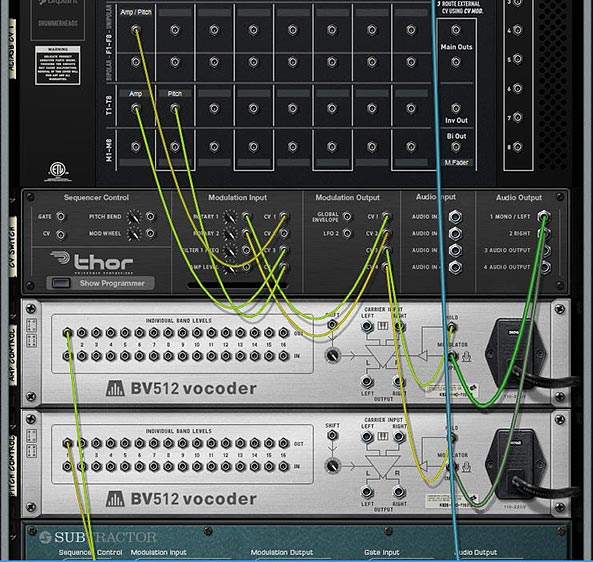
I’m starting backwards here, because this was actually the second idea I had (hence, this is Version 2 in the filenames above). This idea uses two toggle buttons, one for Amp and the other for Pitch. Then, with the proper CV routing and an additional Thor to process the CV, you can map both parameters to the Fader. Click the first Toggle, and the Fader will control the amplitude. Click the Second Toggle, and it switches to control the Pitch. When the Amp toggle is off, you adjust the amplitude. Then click the Toggle button on, and the Amp level is held at the current Fader position. Then click the Pitch Toggle off, and the same Fader now controls the Pitch. Click the Pitch toggle on, and the Pitch is held at the current Fader position. The drawback is that you have to have both Toggle Buttons on to start with, and you can’t turn off both of them, since this would screw up the functionality. One of the buttons always has to be “On.” To get it “set” right again, you need to turn on both Toggles, then, turn one of them off and use the Fader. Sounds confusing, I know. But it’s the most efficient way I’ve found to set it up, as it only uses two Toggle Buttons (aside from the Fader).
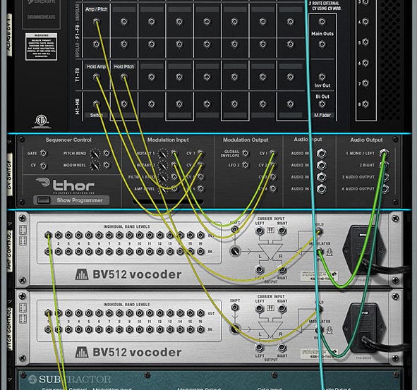
The Back of the rack for the “Version 2” example that uses 2 Toggles to switch Fader Parameters and simultaneously “Hold” the CV values via the BV512 devices.The CV routings from the BV512 into the SubTractor (destination parameters). The Matrix is there simply to “Gate” the SubTractor, so you can hear something and test out the Fader.The settings for the Modulation Bus Routing Section in Thor.
1 Control with 2 Functions (V.1).reason / F1 2-Function Control (V.1).cmb Files:
This next idea uses three additional buttons (aside from the Fader). The two Toggle Buttons act as the Amp / Pitch selection (as above), but a Momentary Button is used to switch between the two Fader states. The benefit of doing it this way is that you can’t screw up the functionality of the Fader in any way. The two Toggle Buttons act to “Hold” or “Freeze” the Level’s position for the selected parameter. The selection of which parameter the Fader controls is determined by the Momentary button. While I think this is a better method in some respects, it suffers from one disadvantage: You can’t tell which parameter is selected via the Momentary Button. There’s no real visual indication to tell you which of the two parameters are selected. This isn’t a big concern when you have only two parameters switched via the Momentary Button, but if you have several parameters you’re cycling through on that Button, things will get confusing quickly (though you could add a visual indicator with the DDL-1 or BV512 Vocoder, but it’s still not perfect – if interested in how this works, see the Kong FX Chain Builder tutorial where I discuss it at the bottom of the page).
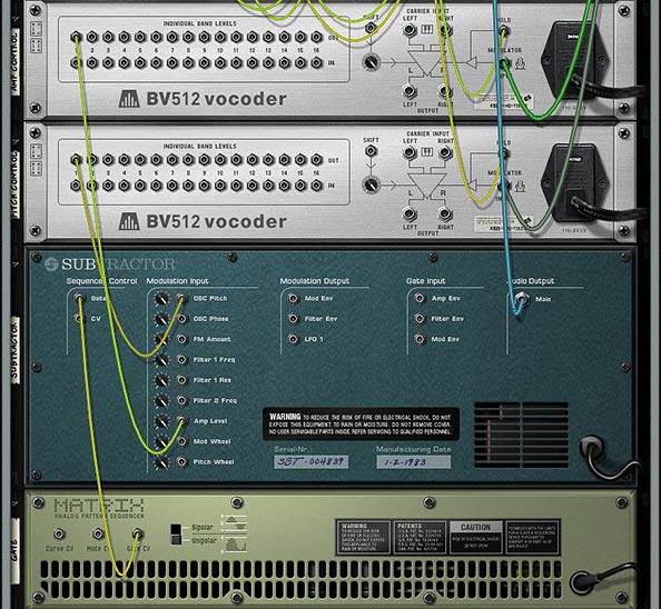
The Back of the Rack for the “Version 1” example that uses 1 Momentary Button to switch Fader parameters, and 2 Toggle buttons that “Hold” the CV values of the Fader via the BV512 devices. Note that the CV coming from the BV512 devices are routed into the SubTractor in the same way as the “Version 2” example (Refer to that image further up in this post).The settings for the Modulation Bus Routing Section in Thor.
How Does It Work?
The engine of this CV trick is the Thor device. What’s happening is that you are sending the CV value from the Fader into Thor, converting that CV value to Audio, then sending it through the BV512, where it gets converted back to a CV value that is sent out by Band 1 to control the SubTractor parameter (Amp or Pitch). The reason you need to convert it to Audio is because the BV512 Modulation input can be “held” — this allows you to “hold” the Fader value via the Toggle buttons on the Alias8. Note that this is also useful for a lot of other things because it allows you to “Freeze” any CV value in place (for instance, you could freeze the value of an LFO at any time by mapping the “Hold” button to a Combinator button, but that’s going a bit off tangent). There are 2 different BV512 devices because you need to be able to “Hold” each parameter you want to control with the Fader.
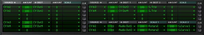
Another thing to keep in mind is the CV amount value of 39 in the Modulation Bus Routing Section on the front of Thor. This seems to be the correct value to correctly scale the “CV > Audio” conversion going out from Thor to the BV512 Vocoder. Note that the Rotary is used to Scale this “CV > Audio” conversion, and then the Fader value is going into Thor and modulating the Rotary, which in turn modifies the CV value being sent into the BV512 device. It seemed like the easiest way to set it all up, and the other benefit is that it doesn’t use any routings or mappings in the Combinator device itself.
A Few Additional Notes:
The value sent to the Fader seems to be Scalar, not Linear. Anyone who knows how the CV value can be sent to the Fader in a Linear way, please let me know.
I also would have loved to have one Toggle or one Momentary button switch between the two Fader parameters (keeping everything in one column in the Alias8), but I honestly don’t think this can be done. However, if you figure out a way, please let me know.
Even though this concept creates a multi-function Fader, there’s nothing saying you can’t set it up on a Rotary control instead, to produce a multi-function Rotary.
Why is this an important concept? Because it extends the functionality of a single Control on the Alias8, and the Alias8 device itself. For example, with a little thinking, you could create 8 different controls on 4 of the Alias 8 Faders, and still have 4 Free faders left over for more tweaking. Or have all the Toggle Buttons switch 8 different destination parameter controls on a single Fader, and free up the other 7 Faders for more tweaking.
Update
Eric Kloeckner was kind enough to expand on this idea and improve upon the above design. He managed to put the whole setup on a single Toggle button to switch the operation of the Fader between the two modulations. It solves the need for having two separate toggle buttons to drive the two different parameters.
I then took his design and tweaked it a little to make it as straightforward as possible. The concept uses 2 Thors to control the Toggle switch. This, in turn switches the Fader between the two modulation controls. The only downside is that you have to first “initialize” it by pressing the Toggle button at least once. But this is a huge improvement. And my thanks goes to Eric for finding a solution to one of the problems that was bugging me. Download the Files here: Alias8-Multi-Function-Fader-v2. There are two files in this zip:
Example File Combinator: Press play, and then toggle between adjusting the Pitch and the Level using Fader 1 on the Alias8.
Template File: Use the Output A / Output B spiders to send CV values to target multiple parameters as you wish. “A” parameters are adjusted when the toggle button is “off” and “B” parameters are adjusted when the toggle button is “on.” Use this setup to create a template where all 8 faders can have multiple-functions if you like.
Note: There’s still a slight discrepancy between the CV input & output. In other words, it’s still not 100% Fader value CV : Destination value CV. You’ll still get slightly off results (where moving the fader on a single CV value will bump up the Output CV value by a value of “1,”). However, this is very slight, and shouldn’t be a problem in most cases.
That’s it for now. Don’t forget that the Alias8 PDF Guide I put together contains many other creative ideas for this Rack Extension, so check it out as well. Happy Reasoning!
With the advent of Reason 7, you get the Audiomatic Retro Transformer Rack Extension for free. This is like Instagram for photos, except it creates musical snapshots that can be applied to the whole mix or individual tracks. So I thought, why not create an FX combinator where you can select different Audiomatic presets using the Kong pads. The added benefit is that you can switch between them in real-time at any point you like using automation. I even added a bypass so that when an audiomatic preset is not selected, the original audio is passed through unaffected. Or, there’s a method to play it parallel with the original loop.
In this tutorial I’m going to go over how to create an 8-way Audiomatic Retro Transformer Switcher using the Pads in a Kong device. You can easily add all 16 on all Kong Pads and then switch between any of them using your Pad Controller or Key Controller. Or you can use a built-in randomizer. This is just one idea I came up with out of a discussion with Kurt Kurasaki on Facebook. So I thought I would share it with everyone.
With the advent of Reason 7, you get the Audiomatic Retro Transformer Rack Extension for free. This is like Instagram for photos, except it creates musical snapshots that can be applied to the whole mix or individual tracks. So I thought, why not create an FX combinator where you can select different Audiomatic presets using the Kong pads. The added benefit is that you can switch between them in real-time at any point you like using automation. I even added a bypass so that when an audiomatic preset is not selected, the original audio is passed through unaffected. Or, there’s a method to play it parallel with the original loop.
You can download the project files here: 8-way-audiomatic-kong-switcher. There’s 2 Combinator files included. One file with an audio bypass, and one without. It requires Reason 7.0, Audiomatic Retro Transformer and Directre.
The Audiomatic Retro Transformer Instantaneous Switcher
Create a Dr. Octo Rex Loop Player. Click the Browse Patch folder icon and open the AC Guitar | Open Strums Key of A 90 bpm.drex patch. This provides a sound source for our Combinator FX setup.
Hold down Shift and create a Combinator. Click the Show Programmer button.
Inside the Combinator, create a Mixer 14:2. Reduce the Level Faders on Channels 1-8 all the way to 0. We’re going to control the volume of these Channels using Kong.
Hold down Shift and create a Kong Drum Designer. Relabel pads 1-8 in the following way:
Pad 1 = Spread
Pad 2 = Radio
Pad 3 = VHS
Pad 4 = Vinyl
Pad 5 = Tape
Pad 6 = Hi-Fi
Pad 7 = Bright
Pad 8 = Bottom
Hold down Shift and create a Directre Audio Router. Turn on all 8 Channels using the Enable buttons. We’ll use this to split the incoming audio out to 8 different Channels on Directre (note that you can also use another Mixer 14:2 for this task, instead of Directre).
Hold down Shift and create 8 Audiomatic Retro Transformer devices. Label them the same way you labeled the first 8 Pads on Kong above. Then switch each device’s Preset to the corresponding label. In this case, we will have 8 Audiomatic devices, each with a different preset. The basic premise is to send audio splits from each Directre output into the Audiomatic, and then send that back out to the Main Mixer and then out of the Combinator.
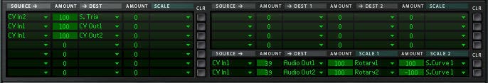
Hold down Shift and create a Thor device. Click the Show Programmer buttton. Name the Thor device “Sequencer.” On the Global panel, set the Pitch Bend range, Polyphony, and Release Polyphony to 0. Relabel Button 1 “Trig Step Seq” and disable both the MIDI & Step Seq buttons. In the Programmer panel, turn off Oscillator 1, disable routing Oscillator 1 from the Mixer to Filter 1 by deselecting the “1” button, bypass Filter 1, and turn off the Global Envelope. Rename Thor 1 “Bass Filter” and Thor 2 “Snare Filter” (see image at right). Enter the following into the first line of the Modulation Bus Routing System (MBRS):
Button 1 : 100 > S. Trig [This allows you to enable the Run button on Thor’s Step Sequencer from Thor’s Button 1]
Still inside the “Sequencer” Thor, set the Run Mode to Repeat, and the Direction to Random. Set the Octave Switch to 4. Create an 8-step sequence where each step is set to subsequent Note values from C1 to G1. Since these notes trigger Kong’s first 8 pads via the internal MIDI Pad assignments, we’re setting up Thor to trigger these Pads randomly.
Still inside the “Sequencer” Thor device, switch the Edit rotary to “Gate Length” and set all 8 steps to 100%. This ensures that switching among Audiomatic presets is instantaneous, as it takes up the full length of the gate. Going from one to the other is a smooth transition.
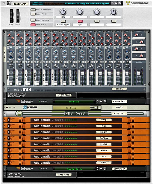
The front panel showing all the devices in the Audiomatic Retro Transformer Combinator patch.
Tab to the back of the rack. Move the left / right Main Output cables from the Dr. Octo Rex to the left / right “Combi Output.” Create a new audio cable pair from the left / right Main output of Dr. Octo Rex to the left / right “Combi Input.” Create another audio cable pair from the Combinator’s left / right “To Devices” to the left / right “Main In” on Directre.
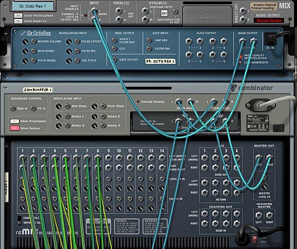
The back of the rack showing the routings between the Dr. Octo Rex and the Combinator, as well as the routings for the Main Mixer.
Send Channels 1-8 left / right Direct Out from Directre into the 8 Audiomatic left / right inputs. Then send the left / right outputs of all 8 Audiomatic devices into the first 8 Channels on the Mixer 14:2.
On Kong, send the first 8 Pad Gate Out CV cables to their respective Level CV In on the Mixer 14:2. However, set it up so that Pads 1-4 on Kong are going into Channels 5-8 on the Mixer, and Pads 5-8 on Kong are going into Channels 1-4 on the Mixer.
Finally, on the “Sequencer” Thor device, send the Note & Gate/Velocity from Thor’s Step Sequencer into the Kong’s CV & Gate inputs. This sets up Kong to be sequenced from Thor.
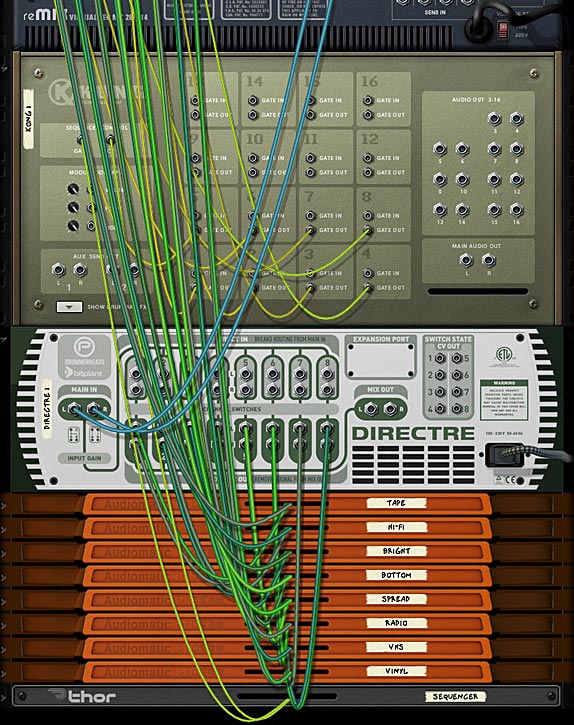
The back of the rack showing the routings between the Mixer, Kong, Directre and the Audiomatic devices.
Tab to the front of the rack. On the Combinator, label Rotary 1 “Rate,” Button 1 “Rnd Sequence,” and Button 2 “Sync.” In the Programmer, select the “Sequencer” Thor device in the Key Mapping area, and enter the following in the Modulation Routing section:
Rotary 1 > Synced Rate : 0 / 20 [Ensures you have access to the full rate of Thor’s sequencer via Rotary 1 on the Combinator]
Rotary 1 > Free Rate : 1 / 2,500 [Ensures you have access to the full rate of Thor’s sequencer via Rotary 1 on the Combinator]
Button 1 > Button 1 : 0 / 1 [Since Thor’s Button 1 sets the Sequencer in motion, this Button turns the Sequencer on when enabled]
Button 2 > Synced : 0 / 1 [Syncs Thor’s Step Sequencer to the Rate to the Song Tempo when enabled]
Set Rotary 1 on the Combinator to 72 (which equals a rate of 1/4 in the Sequencer). Then press Button 2 to set the Sequencer to Sync mode (even though it’s already set up like this by default, it engages the button to operate in Sync).
Press the Run button on the Dr. Octo Rex or press play on the Transport. This starts the Dr. Octo Rex guitar loop. You won’t hear anything though, because there’s no audio bypass. However, when you now press Button 1 on the Combinator, Thor’s Sequencer is set in motion. This, in turn, triggers the Kong Pads to play the first 8 pads randomly (and this, I should add, is wonderful for many different applications). However, you may want to play the Pads manually, or from your Pad Controller, without using the Thor sequencer. You can do this by creating a track for Kong and then going nuts on the first 8 pads. Since the audio is always going through all 8 Audiomatic devices, the switch from Pad to Pad is instantaneous. However, when no pad is pressed, you won’t hear anything. So let’s set up our Combinator so that if the Pads are not pressed, the original audio still passes through. The following explains how to set this up.
Setting up an Audio Bypass
Continuing with our above tutorial, go inside the Combinator and select the Mixer 14:2. Hold Shift down, and create a Line Mixer 6:2, a Spider Audio Merger / Splitter, and a Thor. Name the Line Mixer “Bypass,” the Spider “Bypass Split,” and the Thor “Bypass Gate.”
In the “Bypass Gate” Thor device, set the Pitch Bend Range to 0, the Polyphony & Release Polyphony to 0, and click the Show Programmer buttton. Turn off Oscillator 1, disable routing Oscillator 1 from the Mixer to Filter 1 by deselecting the “1” button, bypass Filter 1, and turn off all the Envelope (Gate Trig) buttons. Enter the following in the first 2 lines of the MBRS:
Audio In1 : 100 > Audio Out1 : -100 > MIDI Gate
Audio In2 : 100 > Audio Out2 : -100 > MIDI Gate
The negative MIDI gate values in the MBRS mean that the original unprocessed sound will shine through when the keys are NOT played. They will also cut the sound when the keys ARE played. In this case, since you have the effects loaded on the keys, the FX signal will take over and you’ll hear the effects processing the sounds while those keys are played. Click the Show Programmer button again to fold up the “Bypass Gate” Thor device.
Tab to the back of the rack, and Move the Directre’s left / right “Main In” audio cables to the “Bypass Split” Spider’s left / right Split Inputs. Send Split 1 left / right outputs on the “Bypass Split” Spider back into the Directre’s left / right “Main In.” Then send a second Split from the “Bypass Split” (Split 2) left / right outputs into the “Bypass Gate” Thor device’s Audio In 1 / Audio In 2.
On the “Bypass Gate” Thor device, send 1 / Left & 2 / Right Audio Outputs into the Channel 1 left / right inputs on the “Bypass” Line Mixer. Move the left / right Master Outputs from the Mixer 14:2 into the Master Outputs of the “Bypass” Line Mixer. Then create a new audio connection from the left / right Master Outputs of the Main Mixer 14:2 to the Channel 2 left / right inputs on the “Bypass” Line Mixer.
The back of the rack showing the routings for the Audio / FX Bypass setup.
Tab to the front of the rack. So far we’ve set up the routing for the bypass. As it stands now, if you press Run on the Dr. Octo Rex, you’ll hear the original loop. If you then press Button 1 on the Combinator, you’ll hear BOTH the original Loop and the Audiomatic Preset playing at once (in a Parallel manner). To set things up so that you don’t hear both at once do the following:
Hold Shift and create a Spider CV Merger / Splitter at the bottom of the Combinator’s device stack. Tab to the back of the rack. Move the “Sequencer” Thor’s Gate / Velocity CV output from the Step Sequencer into the A Split 1 on the Spider CV Splitter. Then create a new CV cable from the “Sequencer” Thor Gate / Velocity CV output into the Spider CV Splitter’s A input. Send another Split (A Split 2) into the Combinator’s CV 1 Input. Change the CV Switch on Input 1 to Unipolar.
Tab to the front of the rack, and in the Combinator, select the “Bypass” Line Mixer in the Key Mapping area. Enter the following in the Modulation Routing section:
CV In 1 > Channel 1 Mute : 0 / 1
When you press Run on the Dr. Octo Rex, you’ll hear the original loop. If you now press Button 1 on the Combinator, the original loop is muted, and only the Audiomatic preset affecting the loop will be heard. Note that with this setup, you cannot play the pads individually via your Pad Controller. If you do, you will still hear the parallel processed configuration with both the Original and processed loop at the same time. However, this gives you two methods to control the Audiomatic switching effect.
That’s it for now. Hope you find this idea useful. Try your hand at creating a 16-way switcher if you like.
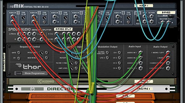
This article will introduce you to the Etch Red RE from http://www.fxpansion.com. This RE is a powerful dual multi-mode filter that can be set up in series or parallel. It also comes with a comprehensive built-in and external modulation scheme that is unlike any other in the stock Reason program. Aside from filtering, it is capable of several tricks such as gating, stereo widening, compression, distortion, LFO wobbling, Tremolo, and Vibrato effects. To top it all off, it comes with the ability to Frequency Modulate the filters (either internally via the 2 built-in LFOs, or externally using an incoming audio source). A lot of power for a very affordable Reason device. So let’s take a walk-through and learn a little more about it.
This article will introduce you to the Etch Red RE from FXpansion. This Rack Extension is a powerful dual multi-mode filter that can be set up in series or parallel. It also comes with a comprehensive built-in and external modulation scheme that is unlike any other in the stock Reason program. Aside from filtering, it is capable of several tricks such as gating, stereo widening, compression, distortion, LFO wobbling, Tremolo, and Vibrato effects. To top it all off, it comes with the ability to Frequency Modulate the filters (either internally via the 2 built-in LFOs, or externally using an incoming audio source). A lot of power for a very affordable Reason device. So let’s take a walk-through and learn a little more about it.
Before I get into the nuts and bolts of the device, let me first point you to the PDF User Manual that you can download. This comes straight from the FXpansion site, and it’s a good idea that you have a read before jumping in. There’s a few pitfalls that you want to avoid when working with this Rack Extension, and while it’s a very nicely designed device, there’s still some areas that might cause you to scratch your head.
Next, let me point out the main features of this Rack Extension in a simple video:
It’s all about Source > Destination = Modulation.
The heart of Etch Red is all the wonderful red knobs scattered throughout the upper (Filters) and lower (Sources) section of the device. These knobs allow you to modulate their associated parameters with one or more of the 10 Sources (selected in the Middle section of the device). Indeed you can modulate one parameter with all 10 sources if you like. Where I can see a lot of people getting tripped up is when you start trying to figure out how to modulate one destination with these Multiple Sources. So here’s a step-by-step tutorial to help you get your feet wet with this concept:
Create a Subtractor, Thor, NNXT, or any other sound-generating device in Reason, or else create a new Audio Track and place some audio on this track. My recommendation is to go for a nice Pad sound to start yourself off. Load up a Pad patch from the Factory Sound Bank if you are stumped for creativity.
Create an Etch Red device underneath so that it is auto-routed to the sound device (hint: Etch Red is found in the Creative FX menu if you right-click under the sound device). If all goes well, the sound device’s Left and Right audio goes into the Etch Red device, and then back out to the Mix Channel or Audio Track.
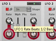
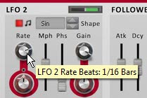
Set the LFO1 Rate to be 1/2 bars and LFO2 Rate to be 1/16 bars. Both are Synced by default. Also adjust their Gain settings to both be set to around 66%. This will remove the harshness of the LFO curve. It’s like a depth or volume setting for the modulation source.
Setting the LFO1 Rate to 1/2 Bars in the Source (bottom) section of the device
Setting the LFO2 Rate to 1/16 Bars in the Source (bottom) section of the device
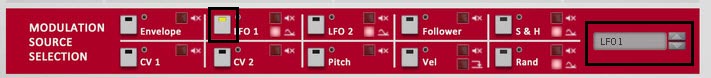
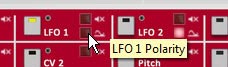
Select a Source from the middle “Modulation Source Selection” section of the device. By default, the LFO1 is selected as a source. You can see this because the little LED within the square icon is yellow. You can also select a source using the drop-down list to the right of all 10 sources. For this example, we’ll use both LFO1 and LFO2 as a source to modulate both Filter Frequencies. Keep LFO1 selected for now. Click the tiny square red LED light just to the bottom right of the LFO1 selector. Turning it off switches the polarity of LFO1 from Unipolar to Bipolar. Leave LFO2 set to Unipolar, which is the default.
The Modulation Source Selection (middle) area of Etch Red. Note that the LFO1 selector is yellow. You can select a source by pressing these square icons, or by clicking from the drop-down list (both are shown here with a black square border).
Setting the Polarity of LFO1 to Unipolar by turning the LED off. This ensures the LFO travels both negatively and positively to affect the destination parameter.
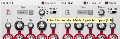
Next, switch the Filter 1 Mode to a 4-Pole High Pass Filter (4H) and the Frequency to 6 Hz (fully left). For Filter 2, leave it set to the Low Pass Filter (default), and set the Frequency to around 350 Hz or so. Also set its Resonance (Rez Rotary) to roughly 25%. Note: The Black rotaries change the parameters. The Rotaries encased in Red circles are used to modulate these parameters. So Black changes the parameters outright, while red is used to modulate them negatively (left) or positively (right).
Setting Filter 1 Mode to a 4-Pole High Pass Filter.
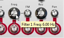
Setting the Filter 1 Frequency to 6 Hz.
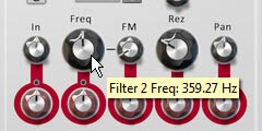
Setting the Filter 2 Frequency to around 350 Hz and the Resolution (Rez) to about 25%.
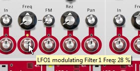
Now we’re set to actually use the sources to modulate the Filters. Using the Red Modulation Rotaries, set the rotaries beneath both filter Frequency parameters to positive 28%. You’ll start to hear the sway of LFO1 affecting the sound as you play the sound device.
Adjusting the Modulation of the Filter 1 Frequency.
Select LFO2 by clicking on the square icon in the middle section of the device or using the drop-down at the far right of the 10 Mod Sources. When you switch over to a new Modulation Source, you’ll notice that both filter frequencies’ Modulation Rotaries snap back to their original values (dead center). You’ll also notice that the small LED circle just above these rotaries turn red. This LEDs indicate that there is another source modulating this parameter. Finally, the previous source’s square selector changes from yellow to red (LFO1 in this case). Switch back to LFO1, and these LEDs turn yellow. Switch back to LFO2, the parameters go back to their default and the LEDs turn Red. Yellow = whatever is currently selected in Etch Red. Red = another value is being used to modulate this parameter.
Note: The one thing that I dislike about working with Etch Red is the fact that when you start creating complex modulations and have several sources modulating a certain Destination, there’s no immediate way to see which sources are modulating the parameter and by how much. You have to click on each source to see how it is affecting all its associated destinations. On the flipside, this does make experimenting with complex modulation assignments quick and you can easily get lost in experimentation. So that’s a plus!
With LFO2 as the selected source, change the Modulation Rotary underneath Filter 2 to a positive 50%. You now have the Frequency for Filter 2 being modulated by both LFO1 and LFO2. That’s pretty much all there is to it.
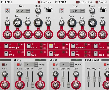
The Final Etch Red Filter, Mod Source Selection, and Sources sections. Note how LFO2 and the LED just above the Modulation rotary for the Filter 2 Frequency are yellow, indicating LFO 2 is the currently selected source, and Filter 2 Frequency is being modulated by LFO2. On the other hand the LED above the Modulation Rotary for the Filter 1 Frequency parameter is red, indicating it is being modulated by another source (in this case, LFO1).
Note: Of course, you can also modulate a Source’s Rate or Gain settings (at least for the sources listed in the top row of the Modulation Source Selection area) by adjusting the red Modulation Rotaries underneath these parameters (in the bottom section of the device). This can also open up some very complex modulations. You can even use LFO1 to modulate its own Rate and Gain. How trippy.
Getting a little more Advanced
So now that we have a grasp on how Etch Red works, I thought I would delve a little deeper into things by using the Envelope source. In order to get the envelope working, you need to send a Gate input signal into the back of the device. And what better way to trigger the envelope than with a Rex loop’s Gate output. So here’s a little video that shows a few techniques along those lines:
Everyone Loves a Dubstep Bass, right (or am I being sarcastic)?
Here’s a great video put together by FXpansion themselves that goes over the process of creating a Dubstep Bass using their device. It’s a little more advanced, but it’s a great way to showcase how some of the CV modulations can be used on the back of their device. And the sound is just cool, so I had to include it here:
More Tips and Tricks
Here are a few other handy tricks you can try out using Etch Red.
Fun with Distortion: Unsync LFO 1 and select it as a mod source. Set its rate to somewhere around 100-600 Hz. Set the output level to -14 dB. Turn up the Drive Mod Rotary slowly. adjust the LFO 1 Rate, Mph, and Drive Types until you find something you like. Great for basses.
Tremolo: Select the LFO 1 as a mod source and click the Polarity LED to make it bipolar. Adjust the Level Mod rotary set to a small amount in either direction for Tremolo.effects.
More Shapes: Create a Malstrom and from the back send Mod A into Etch Red’s CV 1 input. You can now use Malstrom’s 31 waves as a source to affect any Etch Red Modulation.
Dual Filter Gates: Turn off Drive and Filter 2. Set LFO 1 & 2 with “Square” shapes. Ensure the rates are synced, but different for each (ex.: 1/4 & 1/16). Keep the Gain full. Select LFO 1 as a source, and Set Filter 1 to Low Pass (Japan, SVF, or Fatty). Set the Frequency to 6 Hz (full left). Then turn the Frequency Mod Rotary to 100% (full right). Now select LFO 2 as a Source and use it to modulate the same Filter 1 Frequency in the same way (Mod Rotary to 100% – full right). Adjust the depth of both LFOs by adjusting their Gain values.
Auto-Panner: Set LFO 1 to Bipolar. Then use LFO 1 as a source adjusting the Pan Mod Rotary for Filter 1. Adjust the LFO 1 settings to taste.
FM Audio Fun: Try sending audio from a Loop or a synth into the Filter 1 and/or 2 FM inputs. Then on the front, turn up the FM Rotaries, and adjust the Filter Freq & Res to taste. Noise and Saw Oscillators are great audio inputs too (though you may need to raise their volume). For further manipulation, assign an LFO to modulate the FM amount.
Envelopes: To use the Etch Red Envelope, you need to send a CV signal into the Gate CV input on the back. Try sending a matrix Gate CV into the Gate CV input. Now put together a gate pattern in the matrix. Alternately, you can send a Curve CV from the Matrix. Now you can use the Envelope modulation source to modulate any Etch Red Mod Parameters.
Key Tracking your Filters: To use the Etch Red “Key Track” feature, create a Sequencer Track for Etch Red. Then copy MIDI data from another Track (some monophonic data works best). Then reduce the Filter Frequency. When you play back the Sequencer, the Filter will follow the MIDI track, and will in essence be following the musical track from which you stole the MIDI data. Or you can just play along on your keyboard to track the Filters.
Internal Pitching: Try sending the LFO 1 CV output to the Pitch CV input on the back of Etch Red. Then turn on Key Track on the front, and set up your Filter. Choose a Fatty LP filter for a nice bassy sound. Set Freq to about 185 Hz, Rez to 70%, and set LFO 1 Rate to 34 Hz, Free-running, and Mph to about 77%. Oh yeah, some nice Bass Wobbling.
Hope you enjoy Etch Red as much as I do. It’s capable of quite a lot. If you have any other ideas, tips and tricks, please share them with the class.
Reason is one heckuva great program. Reason is the reason I’ve created all these tutorials. Perhaps one of the most overlooked aspects to the program is the creation and usage of Templates. These amazing time savers can reduce your time to creating tracks immensely, and if you don’t use them now, hopefully you’ll realize their value after you read this article, and use them as an integral part of your process. So let’s get busy!
Reason is one heckuva great program. Reason is the reason I’ve created all these tutorials. Perhaps one of the most overlooked aspects to the program is the creation and usage of Templates. These amazing time savers can reduce your time to creating tracks immensely, and if you don’t use them now, hopefully you’ll realize their value after you read this article, and use them as an integral part of your process. So let’s get busy!
You can download the project files here: 3-templates. They contain 3 Templates that I have used in the past. The first template Album Session – Dark is exactly that. It’s a template I used when I was coming up with the songs for my “Dark” album. It contains all the starting things you would need (Drums, Bass, and two audio tracks). I used Redrum channel 1, 2, and 3 to mix together 3 bass drums. Channel 4 & 5 were for the Snare sound, and channel 8 & 9 for the Hi Hat. The Bass Drum is processed through a Pulverizer and is also used to sidechain the Bass. I put a simple drum track in the Redrum Pattern Sequencer and Bass track in the Main Sequencer so you can see the setup. The audio tracks were used to include samples that I stretched out to be a super long length and in effect created the Pad sound. I also sometimes threw in an Alligator to apply to the Bass or the Pad sound on the audio track. There’s also some basic mastering in the Master Insert device, and two Reverb Send FX. It’s pretty basic, but gives you an idea of how to set up a template for use as the main song starter for an entire project. There’s a million different directions you could go with this idea. Normally, after loading this template, I would change out the drum and bass sounds, and create a new pattern (or several) in the Redrum. I would also play a different MIDI pattern on the Main Sequencer for the Bass, and change the Bass instrument. Essentially, it’s just an empty shell. It’s up to you to fill it with your own MIDI, Patterns, and instruments.
The second template is the ReDrum Submix which I used to use prior to Record and Reason 6. It submixes a Redrum into its own 14:2 Mixer, and then routes that mixer to the Main Mixer for the song. Again, a simple pattern was added into the ReDrum to give you an example. This also uses two BV512 Vocoders as Spectrum Analyzers to monitor your sound. The third template, Sound Design is one that I still use when I want to create some new patches and sounds in Reason using the stock 3 synth devices. There’s one of each of these devices, and all the parameters are set to zero. In addition, there’s a Matrix sequencer attached to each one. This way, you can start from the ground up on any device you wish (you just need to give the correct device focus – on startup, the Subtractor has focus). Since all parameters are set to zero, you have to build the whole patch from scratch. The Matrix devices are in there so that you can use a simple pattern to play the device, instead of playing via your key controller. This can make it easier when you want to focus on changing parameters and let the Matrix handle the device playback. Note that you should also test out your patches using the key controller, as this can help you with things like key range, velocity settings, etc. Either way, you can use the Matrixes or not.
What is a Template?
A Template, put simply, is a Reason song file (.reason). It cannot be any other file type. It is used as a starting point for document development (usually a song; however, it can also be used as a Mastering Template, Sound Design template, Loop Template, or any other purpose that you have for Reason files). It can contain anything that can be saved in a Reason file, which pretty much means anything and everything in the Reason universe.
The concept of Templates is nothing new. You find them in Microsoft Word, Excel, and Adobe products, such as InDesign as well. If you think about what happens when you first use any of your programs, you usually start off with a New, empty document. Then you perform a few common tasks. For example, you open up a new Word document to a blank page, then you may change your styles to reflect what you want to write, show hidden text to show you paragraph markers, maybe add a specific layout, create a two-column setup, write a basic introduction, and add a Table of Contents. After a while, you realize that you keep performing these same tasks at the start of every new document. Well, what if instead when you open that new document, all of these tasks were already performed, allowing you to “skip over them” and get straight to writing the content of the document. This would save you a lot of time right?
Enter the concept of the “Template.” The Template takes all of the common tasks that you perform at the start of a new document, and puts everything in place for you so you can get right to work. In the Reason world, this might be including a set of Send effects, or your own personal mastering template before the audio output goes to your audio card. If you use the same drums or bass or other instruments, you can include them and they, in turn, can have their own inserts. If you find you are always including 3 audio tracks in every song, you can add the tracks and have them ready to go the next time you start off your document. Channel strip settings, MIDI data on the sequencer, automation, Blocks, CV and Audio routings. All of these things can be saved into a Template.
Then, the next time you want to start a song, you can open up your Template and get to work unfettered by all the repetitious and dull start-up nonsense. It’s the equivalent to starting off a road race half-way to the finish line. While everyone around you starts way back at the starting gun. Then, once you’ve added your new (unique) work into the mix, and save your document, you’re NOT saving over top of the Template. You’re saving your work to a new file. It’s like using “Save As” in reverse. Instead you’re using “Start As” to start off a new document as a Template. And this is an important point. Your template remains the same and is stored into its own special folder. When you open it to start a new document (from File > New from Template), you are opening a “copy” of that Template document. When you then go to File > Save or File > Save As, you saving this “copy” of the file, not the Template itself. The only time you can overwrite a Template is if you actually go into the Template folder and save over your Template, or delete the Template from the Templates folder directly.
Navigating Templates
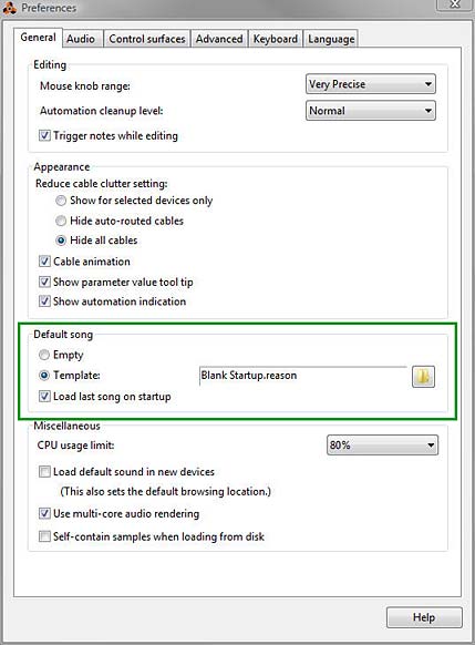
Let’s start with a simple premise: A lot of users don’t know where the templates file is stored. Furthermore, most people confuse a “Template” with a “Default Song.” These are not the same thing. The Default Song can be accessed from the Edit > Preferences folder (on the General tab), as shown below:
The Default Song options from the Edit > Preferences > General Tab Menu
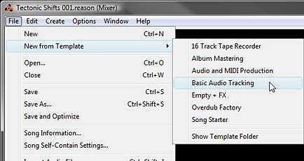
The Default Song parameters set up what you want to happen when you open Reason. If you want to always open Reason with a Template song, you can do so by selecting the “Template” option. However, this is very different from the Templates you can access once Reason is open. In this case, a Template is accessed from the File > New from Template menu, as shown below:
The File > New from Template sub-menu where you can access all your stored Templates.
You’ll notice a few things. First, you already have a few default templates stored here, which are nice to look at and explore. You might also find a Template or two that fit your own working process. Second, you’ll see that there is a “Show Template Folder” option at the bottom of the list. This is handy to point you to where your Template Folder is on your machine (I’ll get to this in a minute, as it’s different for different operating systems), and also a handy way to open the Template folder and delete Templates quickly (again, more on this below). Third, and most importantly, after a while the inevitable question will pop into your head: “How do I add my own Templates”?
So let’s deal with the question: “Where are your Templates stored”? All templates are stored in the following folder. Note that your location varies depending on your operating system:
PC (Win Vista)*:C:\Users\[User Name]\Application Data\Propellerhead Software\Reason\Template Songs
PC (Win7)*:C:\Users\[User Name]\AppData\Roaming\Propellerhead Software\Reason\Template Songs
MAC (OSX):\user\Library\Application Support\Propellerhead Software\Reason\Template Songs
* Note that in Windows, this folder may be hidden. You will have to unhide your system folders in order to see it. In Windows 7, open your “Control Panel > Folder Options > View Tab,” and select the “Show hidden files, folders, and drives” radio button.
* Note also that if you have moved the “Users” folder or mucked about with the system folders in Windows, you can open an Explorer window and type “%appdata%” into the path entry (search field) at the top. This will open up the “Roaming” folder. From there, you can navigate to “Propellerhead Software/Reason/Template Songs.
So once you have your template set up the way you want, you’ll need to first save your song into the above folder. Then you can open it from File > New from Template > [Your Template File].
Note to Props: It would be nice to have a direct command under the File menu that allows you to “Save As Template” which opens the “Save As” dialog directly navigated to the “Template Songs” folder. This way you could easily save any document you’re working on into the Template Songs folder. Just a thought.
Building a Template: The Checklist
Everyone will have their own purpose for creating and using a Template. As you create your template, it’s a good idea to look at the checklist below and cross out those areas that don’t pertain to you, and check off those that do. Doing this while you create a Template will ensure you don’t forget something in the process. As you create more Templates, you’ll need to rely on this list less and less. I might have missed a few things, and if so, let me know and I’ll update the list below. Print it out and make a few copies the next time you create your Template.
Purpose of Template? (Song Structure, Mastering, Startup document)
Edit > Remote Override settings
Master effect inserts (Rack)
Send effects (Rack)
Audio channel devices (Rack)
Audio track (Sequencer)
Audio track clips (Sequencer)
Audio track clip labels (Sequencer)
Audio track clip colors (Sequencer)
Audio data in the clips (Sequencer)
Mix channels (Rack)
Instrument devices (Rack)
Instrument track (Sequencer)
Instrument track clips (Sequencer)
Instrument track clip labels (Sequencer)
Instrument track clip colors (Sequencer)
MIDI data in the clips (Sequencer)
Instrument device inserts (Rack)
Pattern devices (Rack)
Pattern data in the devices (Rack)
Pattern track (sequencer)
Pattern lanes (Sequencer)
Pattern lane clips (Sequencer)
Pattern lane clip labels (Sequencer)
Pattern lane clip colors (Sequencer)
Blocks (Sequencer – Block mode)
Blocks (Sequencer – Song mode)
Block labels (Sequencer – Song mode)
Block colors (Sequencer – Song mode)
Audio routings (Rack)
CV routings (Rack)
Mixer Channel Strip settings for each device (Mixer)
Master Channel Strip settings (Mixer)
Master Bus Compressor settings (Mixer)
Device labels (Rack)
Screen Layout (Rack/Mixer/Sequencer combined or split, F4 Keyboard on/off, etc)
Now for the naming of your Template file. Create a naming structure that you will understand. It may not seem important right now, and yes you can always change file names later. But if you start off organized, you’ll benefit as your Template list grows in size. Since you can’t currently create folders for hierarchy, the Template name becomes even more important. So keep the first word in the file name reserved for hierarchical purposes. Here’s what I recommend as an idea:
Mastering – Dubstep – Brickwall
Mastering – Dubstep – MidSide
Mastering – Electronic – Kompact
Mastering – Rock – Subtle
Mastering – Rock – Wide
Startup – Empty – 3 Windows
Startup – Empty – 1 Window
Startup – Sound Design – Combi
Startup – Sound Design – Synths
Structural – Electronic
Structural – House – ICVCVO
Structural – House – ICVBCVBO
Structural – Rock – CCVCVO
This type of hierarchy is merely a small example. It provides for the three main reasons for using templates at the top level: Mastering, Song Startups, and Song Structures. The second level provides for the type of genre you’re working on. And the third level provides the type of Mastering or the type of Song Structure (I=Intro, C=Chorus, V=Verse, B=Break or Interlude, O=Outro). Song Starters are a little different. I usually use the second level to provide the focus, and the third level to narrow that focus. This will make navigating your template folder easy and save you time when looking through a very large list. You could even add numbers if you have two different templates for the same type of Mastering or Song Structure Template. If you do this, the numbering should probably go at the end as a fourth level. And with everything, this is only a suggestion for keeping things neat and tidy.
I also didn’t include a category for “Album Mastering” but of course you can add this as well. There are two or 3 default templates that show how Templates can be used in this manner. In this case, you add the amount of audio tracks (Audio Channel devices) into your Template document. Each track represents a song in your album project. You then add the appropriate sends/mastering devices that will be used for all the tracks. Then anytime you have a project, you open up that document and start adding your tracks into the existing channels. In this way Reason becomes your track recorder/master.
Templates for Power Users
Once you get comfortable with Templates, you’ll realize you can create as many of them as you like. Perhaps you’ll create a new Template for each album or EP project. Or, you might want to create a few different templates for different genres or recording situations. The point is, you’ll start developing your own Template folder. There’s a few key things that I would recommend if you’re going to become a Power Template User:
Unless you use any of the default Templates regularly, create a “Default” folder in your “Template Songs” folder and move them all into this folder. Note: Any folders created under the “Template Songs” folder won’t show up in the “File > New from Template” subfolder in Reason. Then enter any Reason song files you want to use as Templates into the main “Template Songs” folder. These songs will show up in the File > New from Template submenu, and it’s dynamic, meaning that you don’t have to first shut down and then restart Reason in order to see them in the submenu. They are just magically there once you place them.
Note to Props: It would be nice if the folder hierarchy does show up under the File > Template Songs folder, in the event that power users want to categorize their Templates. Just a thought.
Remote Overrides (under Options > Remote Override Edit Mode) can also be saved with your Template. This means that you can use Templates as a “Remote Template” for any controllers you have connected to your computer. A nice handy way to instantly call up a Controller setup (especially for live recording).
I have it on pretty good authority that some artists use Templates to create their own “song structure” templates, complete with instruments, sends, inserts, mastering, MIDI, etc. Then they use these templates to switch out instruments. This becomes their entire process, creating several songs that have the same basic structure but sound different. While this is perfectly valid and I wouldn’t argue against doing this (I think it’s quite ingenious actually), I would add a word of caution. Templates are powerful things. But don’t let them stop you from starting off your songs with a completely empty slate as well. It’s the only way to grow and enhance your skills. So if you DO end up going in this direction, don’t neglect the artistic or creative side of starting projects off without a Template, at least every now and then.
As with anything you do on your computer, make a backup of your entire “Template Songs” folder somewhere outside this folder and outside the evil clutches of the Reason install (and preferably on a completely separate external drive or backup drive). I’m joking of course, as I don’t know if any files in this folder get overwritten. It’s quite possible that on your next install, the default Template songs will merely be added back into the folder in a gleefully chummy way next to your other personal Template files. But if not, or if something crashes, you can just copy this backup folder and paste it over the post-installation “Template Songs” folder. And hey, it’s backup. You should do this regularly!
So that’s Templates in a nutshell. I really didn’t think this article would end up being so long. But it seems there were a lot of things to discuss. Hopefully this helps you understand them, navigate through them, create them, and use them. So go forth and create some cool templates and please share them with me if you have some great ideas. I’d love to take a look at your inner workings. If we all shared a few templates, we’d all raise our game and learn a few things along the way. So let’s see what you’ve got! All my best and happy music making.
Matt Black (aka: Jiggery Pokery) has done it again. Instead of providing a new ReFill, he has dazzled us with a new Rack Extension: Shelob, a 4-input, 16 stereo /32 mono audio output Splitter. Think of it as 4 Spiders locked together in a nice compact unit, but with a few extras. And all for the low price of $9.00 USD. In this article, I’ll discuss a little about what you can do with this baby.
Matt Black (aka: Jiggery Pokery) has done it again. Instead of providing a new ReFill, he has dazzled us with a new Rack Extension: Shelob, a 4-input, 16 stereo /32 mono audio output Splitter. Think of it as 4 Spiders locked together in a nice compact unit, but with a few extras. And all for the low price of $9.00 USD. In this article, I’ll discuss a little about what you can do with this baby.
You can download a few free patches here: Shelob Patches. These patches outline a few ways you can use Shelob to crossfade, parallel process, stripe a range of effects splits played via keys on your MIDI keyboard, group splits, create a fade in / fade out combinator, etc. Use them as templates and lessons in how to route things up in Shelob. See the videos below for a little more about how Shelob works.
First, let’s take a look at what Shelob replaces or improves upon:
Reason’s stock Spider Audio Merger/Splitter from the back, indicating the split side with 1 audio input and 4 audio split outputs. This is what Shelob replaces.
Next, let’s take a quick look at Shelob from the front and from the back:
The Front of the Shelob Audio Bypass SplitterThe Back of the Shelob Audio Bypass Splitter
The following showcases the differences between the original Spider Audio Merger/Splitter and the Shelob:
Uses 1 device rather than 4 Spiders. Note that the Spider can take 1 input signal and split it 4 ways, as well as take 4 input signals and merge them into 1. On the other hand, Shelob can take four input signals and split each of those signals 4 ways (or any combination of those, for example, you can take 1 input signal and split it up to 20 ways; 16 straight outputs and 4 pass-through outputs). There is no merging capability with Shelob, though I have it on good authority that a merging device is on the way.
Off/On of each of those 4 channels and 16 stereo/32 mono outputs can be automated
Each set of 4 inputs can be used as a pass-through in order to create “Split Groups” that can be turned on/off
Ability to fade the signals in or out. This opens the door to creating crossfades between signals on Shelob, and fade in / fade outs of any audio signal. The Fade is “global” so it affects all signals sent in or out of Shelob. The fade can be anywhere between 1 millisecond to 20 seconds.
Ability to “Stripe” the signal. This means you can take one input signal and send it to all 20 outputs without any additional inputs or routing.
All switches on the device can be automated or programmed in the Combinator to be on / off. In addition, the fade knob can also be automated or programmed to a Combinator control.
Here’s a quick introduction to the device:
Fade Knob
The fade essentially determines how long the sound “fades out” after you turn that specific channel from “On” to “Off.” In the default position, turn any channel off and the sound stops immediately. With more fade, turning any channel off will let the sound fade out slowly. This also works both ways, so you can “fade in” a signal when you turn a specific channel from “Off” to “On.”
Fade is global, so it affects all channels, and it can be automated. But of course you can create multiple Shelobs to control fade on some channels and then fade differently on others.
From Matt:
Fade times work both ways – switch on (fade in), and switch off (fade out).
As Rob says above, Fade time can be automated as required.
With a maximum fade time of 20s, you could even stick a Shelob on your master outs, or just before Ozone if using that for dithering, and flick a switch for fade in at the start and fade out at the end
The Fade knob is 0-100 milliseconds in the white area, and 101-20000 milliseconds (20 seconds) in the green area. This means you can create a fade 0-20 seconds long. To create a simple crossfade between two signals, for example, program a Combinator Button to switch Channel 01-A to go on/off and Channel 01-B to go off/on. The button is now used to crossfade between the two signals. Program the Rotary 1 to adjust the Fade knob and use it to determine the fade time from 0-20 seconds. This makes it one of the easiest ways to crossfade between two audio sources or two effects.
Here’s a video that shows you how to Crossfade and parallel process your audio signals:
Stripe Switch
With the Stripe switched turned on, you can send one audio signal into Channel 1 input, and then split that signal on all outputs (A through P) at once, without any further input signals. This means you don’t need to Chain an output split to the next 3 Channels (for example, from A-1 to Channel 2 input). With Stripe Off, the Channels can be used separately (as if you have 4 independent Channels in Shelob, or more to the point, the Shelob acts more like 4 Spider Audio Splitters in one).
Incidentally, if you want to use Shelob exactly as you use the Reason Spider Audio Splitter, keep Stripe off, and turn on all output splits (A through P). Now, all splits are open or on, and you can send four different audio inputs into all four Channels and split them into their respective splits.
Also, with the Pass-Through, you gain an additional output on each Channel, meaning that you have 4 extra Splits (for a total of 20 outputs). Though this is not the intended use of Pass-Through (discussed more below), you can indeed use it this way.
Again, from Matt:
While you can get 20 ouputs, the recommended setting here is to not connect the Pass jacks, but you can do.
Put your input into Channel 1, and turn on Stripe. Channel 1 will then be sent to Channnels 2, 3 and 4. Now you can turn each Channel off/on either as a Channel group with it’s Pass Switch (hence why it’s recommended not to use the Pass Jacks), and you can turn all Channels 2, 3 and 4 on and off simultaneously via the Stripe switch!
This opens the door to a lot of possibilities. Here’s a quick video to show you how to use the Stripe Feature and showcases a few of the included Combinators:
Inputs 1, 2, 3, and 4
Simply, this is where you input your audio source(s). Pretty straightforward. There are four Channels, and you can source four audio signals.
Pass-Through 1, 2, 3, and 4
Pass-Through allows you to send audio from one Channel to another. Since each Pass-Through has an on/off switch on the front of the device, this means you can “group” your splits and turn on/off all four splits of each channel with one switch. To use it, simply ensure you have an audio source going into a Channel (let’s say Channel 1, for example). Then send the Pass-Through from Channel 1 to the input of Channel 2, 3, or 4. Now, the audio source into Channel 1 is also input into Channel 2, without the need to steal a split from Channel 1 to chain Channel 1 to Channel 2 (via split A, B, C, or D). This is one other advantage Shelob has over Reason’s Spider Splitter.
Here’s a video to show you how Pass-Through operates:
Splits A through P
The Splits take whatever Audio is input into a Channel (or from a previous Channel, if Stripe is turned on), and sends it out to whatever destination you like. You can send a split out to other effect(s), or straight to a Mixer Channel or to a Mix Channel device, or other splitters. The audio can be sent to whatever audio destination you like.
That’s the Shelob utility Rack Extension in a nutshell. Hopefully, this gives you some ideas and helps you understand how to use the device. Check out the attached Combinator patches and have some fun playing with it. For less than the price of an iTunes album, it’s well worth the expense to get a little more functionality out of audio splitting. Happy Reasoning! And thanks so much Matt, for such a great addition to the Rack. Cheers mate!
With the introduction of Rack Extensions from Propellerhead, we see a major shift of the company into the Plugin arena, although Rack Extensions are expressed as “plugins done right.” And the Props have introduced 3 new Re devices (Radical Piano, Polar, and Pulsar). Not too bad for a point release. Instead of focusing on the 6.5 release itself, and debating the cost (it’s been done to death in the forums), I thought I would start by taking a tour of Pulsar, a device that is free for 3 months, and $49 thereafter. Hopefully, by the end of this article, you’ll see why the price is justified. Pulsar is simple, fun, and capable of some very unique sound ideas. Let’s take a look at why this is the case.
With the introduction of Rack Extensions from Propellerhead, we see a major shift of the company into the Plugin arena, although Rack Extensions are expressed as “plugins done right.” And the Props have introduced 3 new Re devices (Radical Piano, Polar, and Pulsar). Not too bad for a point release. Instead of focusing on the 6.5 release itself, and debating the cost (it’s been done to death in the forums), I thought I would start by taking a tour of Pulsar, a device that is free for 3 months, and $49 thereafter. Hopefully, by the end of this article, you’ll see why the price is justified. Pulsar is simple, fun, and capable of some very unique sound ideas. Let’s take a look at why this is the case.
You can download the project files here: pulsar-synths. This zip file contains some Combinators and .reason files which go through some of the concepts I’ll discuss below.
Starting off with a simple LFO
At it’s most basic, Pulsar is a Dual LFO. But when you first add a Pulsar to your project, you’ll only be using LFO 1. In many cases, this may be all you need. And if that’s the case, you may be wondering why you would need yet another LFO in the Reason arsenal? Doesn’t Thor, Subtractor, Malstrom, and even some other devices have one or two LFOs that can be used (and have been used) by many since the birth of Reason? Sure. But Pulsar delivers something the other LFOs do not (apart from Pulveriser). It comes with a “Lag” feature. Furthermore, it comes with two other unique features: “Phase” and “Shuffle.”
To recap, the “Lag” feature is an LFO filter which smooths out the shape of the LFO. If you are using an LFO with a sharp edge (Square or Stepped, for example), increasing the Lag feature curves those sharp edges, and can reduce a lot of the abrupt “clicking” that can result from these LFOs.
“Phase” is used to shift the LFO forward or backward, kind of like a pulse width modulation for your LFO. Look at Thor’s Analogue oscillator set to a square wave. The Mod parameter works the same way by shifting the LFO forward or backward (widening or narrowing the LFO). When using two similar LFOs in Pulsar and adjusting their Phases (or automating Phase movement in real-time), you can create some really interesting modulations with the LFOs.
Finally, there’s a parameter we’ve seen time and time again, though not in an LFO: “Shuffle.” This parameter shuffles the LFO, making the movement or LFO automation more erratic. Keep in mind though, that while “Shuffle” provides some randomness to your LFO cycles, the cycles themselves will always be in sync. In other words, the start and stop of the waveform will be random, but their duration will always equal the time cycle that you set up in the timing of the LFO. And it’s important to note that “Shuffle” works in 2-cycle pairs. So looking at a 2-cycle waveform set to 1/4 Tempo Sync means that you have two cycles of the wave that equal 1/4 each. Cycle 1 will always start at the beginning of the cycle, but can end anywhere within both cycles. Then cycle 2 starts and always ends at the end of both cycles. Kind of an interesting strategy if you ask me. But putting the theory aside for a moment, the best way to get a feel for it is to try it out for yourself.
All three of these parameters are fairly unique to Pulsar. And so it might be worth your while to try using this LFO on it’s own the next time your modulation calls for it in your track.
There’s also lots of other interesting things you can do with Pulsar: Sync LFO 2 with LFO 1, Have the Level of LFO 2 affect LFO 1 (AM), have the Rate of LFO 2 affect LFO 1 (FM), trigger the envelope via LFO 2, and this doesn’t begin to get into the CV / Audio modulations on the back of the device. Using all of these features allows you to set up some very complex modulations and even use Pulsar’s LFOs as Oscillators to create some very unique sounding (somewhat Analog-style) synth instruments. We’ll dig into that further below.
But before going further, you should definitely check out the introductory video from the Props on how Pulsar can be used as an LFO and how those LFOs can be used as Oscillators. This is perfect for getting your feet wet with the device. And the final song result at the end of this tutorial is truly inspiring. So before doing anything more, let’s take a first look at Pulsar:
Accessing the Pulsar Patches
Pulsar can’t load or save patches. However, you can contain a Pulsar (along with any other devices to which Pulsar is connected) inside a Combinator and then save the Combinator. And this is a great time to bring up the fact that Pulsar comes with a wide variety of effects and instruments that were put together by some very talented patch designers. Here’s how you can access them:
Right-click on the Rack and select “Create Instrument” or “Create Effect,” depending which option you want.
Right-clicking on the rack and selecting “Create Instrument” or “Create Effect”
The Reason Browser opens. Notice the “Rack Extensions” option under the “Locations and Favorites” area on the left side of the window? Click it, and you’ll see all your loaded Rack Extensions displayed on the right side.
The new “Rack Extensions” stock patch bank in Reason 6.5
From this list, select Pulsar directly by double-clicking it and navigating down the folders to all the available patches. Alternately, you can click the plus (+) sign and drill down to the patch you like.
The Pulsar stock patch bank expanded on the right side of the Browser window.
Double-click on the patch of your choice to open it in the Rack.
The Pulsar patch loaded into the Rack (with a great new Combinator backdrop by the way – nice job Propellerheads!).
Of course, if you’re saving your own patches, you’ll have to save them to your own computer location. All Pulsar patches need to be saved as a Combinator device. So all the patches you’ll find underneath the Pulsar stock patches are Combinators.
I strongly urge you to have a look at these patches. They showcase how you can use Pulsar in all manner of ways. There’s a way to use it as a dual gate, dual wah, LFO filter wobbler, FM, AM, etc. So opening the patches to get a feel for Pulsar is a great way to learn how to use it.
Pulsar as Dual Oscillators: Cheap on CPU, not Cheap on Sound.
And now for the major coup. Yes, you can use Pulsar as a dual Oscillator to create all manner of synth sounds. Trust me, I’ve tried. For those using Reason essentials, this provides a great alternative to the Subtractor synth. You now have a second synth inside Reason. And for those using Reason, you’ll be thrilled to know you not only have a simple synth, but process this synth through Thor, and you have a very amazing sound generation tool that is quite unlike the other sounds in Reason (whether that sound is good or bad is something I’ll leave for you to decide, as it’s a raw aliased sound that some like and some don’t). But nevertheless, it’s a unique sound with which you should experiment.
First, the video:
Let’s start off slow and figure out how to use Pulsar as a synth on its own. Since Reason Essentials doesn’t come with Thor, this is really the only way to go for that group of users. And yes, you can most definitely use Pulsar as a synth on its own. This is really great for Bass sounds, and in my opinion, this is where it shines. So let’s get started with a very simple setup:
Right-click on the rack and select Utilities > Combinator. Inside the Combinator, right-click and select Utilities > Pulsar Dual LFO.
Flip to the back of the rack and send LFO 1 Audio Output 1 from Pulsar to the Left “From Devices” Combinator Audio input. Then send LFO 2 Audio Output 1 from Pulsar to the Right “From Devices” Combinator Audio input. This way, LFO 1 produces the sound for the Left side of the stereo field, and LFO 2 produces the sound for the Right side of the stereo field.
The Routings from the Pulsar to the Combinator
Open the Combinator’s programmer and select the Pulsar device. At the bottom left side of the screen place a checkmark in the “Receive Notes” checkbox. This allows you to play the Pulsar through the Combinator’s MIDI note input.
Selecting the Pulsar device in the Combinator’s Programmer and ensuring it “Receives Notes”
It’s important in this kind of setup to ensure that the parameters for both LFOs are set exactly the same, otherwise you’ll hear differences in the sound coming from both the left and right sides of the stereo field. Start by turning Off the Tempo Sync for LFO 1, and turn On LFO 2 (On/Off button). Switch LFO 1 and LFO 2 Waveforms to Sawtooth waves. Then reduce the “Level” rotaries to 0% for both LFOs. Increase the Shuffle knobs to 70% for both LFOs.
In the Pulsar Envelope section at the right side of the device, reduce the Release amount to zero (0) ms. Increase the Envelope Rate for both LFOs to 100%, and increase the Envelope Level to about 60% for both LFOs.
If you play the Combinator through your MIDI keyboard at this point, there is no key scaling. No matter what key you play, you’ll hear the same note pitch. In order to scale the keyboard, you must turn the MIDI KBD Follow knob on Pulsar fully right to 100%. Once you do that, you’ll have yourself a nice little patch that should play a pretty cool bassline in the C-1 to C2 range.
The Pulsar’s front panel setup
Advanced Pulsar Synth Processing through Thor
Let’s take it up a notch:
There’s two ways you can process Pulsar through Thor: Both methods involve sending the audio outputs from LFO 1 and LFO 2 into Thor and then entering the following two lines into Thor’s Modulation Bus Routing Section (MBRS):
Audio In1 : 100 > Filt1 In
Audio In2 : 100 > Filt1 In
As long as both the Pulsar and Thor are receiving notes, and are inside a Combinator, you’re all set. Ensure that both LFO 1 and 2 on Pulsar are not Tempo Synced, and turn the rates all the way up (fully to the right). Also keep the Pulsar Envelope settings at their default, and turn the MIDI KBD Follow knob all the way right to 100%.
The cool thing about this setup is that you can use Thor’s Portamento, Shaper, Filter 1, Filter 2, Amp Envelope, Amp section, and pretty much everything else in Thor to shape the sound of the Pulsar LFOs. In this instance, you’re simply replacing Thor’s Oscillators with Pulsar’s LFOs (which are used as Oscillators).
One thing to keep in mind with this approach is that since you’re processing the audio through the Amp section, the levels of your audio are going to be adjusted using both the Thor Amp Gain and Pulsar’s LFO Level controls. So watch those levels!
The second approach builds on the first and bypasses most of Thor by sending the audio into Filter 3. So after you’ve entered the two audio lines in the MBRS as above, enter the following two lines in the bottom right two MBRS entries as follows:
With this approach, you’re bypassing everything between Filter 1 and Filter 3. This means no Shaper, no Filter 1 and 2, and normally, no Amp Envelope either. However, since you’re scaling the audio using the Amp Envelope explicitly in the MBRS, then you can still use the Amp Envelope to adjust your audio. The advantage is that you gain a 4-stage envelope (Attack, Decay, Sustain, and Release) with Thor, instead of a 2-stage envelope with Pulsar (Attack and Release). Also, you can use the Delay and Chorus FX in Thor to affect the synth sound.
One note though. You can’t use Thor’s Amp section for any adjustments. So all the volume control resides in Pulsar’s LFO 1 and 2. And it suddenly occurs to me that all of this is in the video, so check it out if any of this sounds esoteric to you. Have fun!
Oh and in case you missed it, here’s James Bernard’s take on Pulsar. Pretty awesome sampling technique. Don’t miss this one either:
The downside is that you need Reason to do these wonderful Thor processing tricks. No can do with Reason Essentials. So upgrade already!
So that’s how you set up Pulsar as a synth. Try out the different waveforms and have a blast making some new sounds. And if you have any other Pulsar tricks, be sure to let us all know. Cheers!
In this fifth installment of my series on better patch design, I thought I would take a much-needed break from all the theory and synth jargon, and instead focus on some creative Thor synth ideas. I can almost hear the collective yawn after reading the last few articles. So let’s spice it up with a few videos that showcase some of the concepts we’ve talked about, but more importantly, let’s just have some fun fiddling around in Thor.
In this fifth installment of my series on better patch design, I thought I would take a much-needed break from all the theory and synth jargon, and instead focus on some creative Thor synth ideas. I can almost hear the collective yawn after reading the last few articles. So let’s spice it up with a few videos that showcase some of the concepts we’ve talked about, but more importantly, let’s just have some fun fiddling around in Thor.
You can download the project files here: better-patches-part5. This zip consists of a few Thor patches and demo .reason files that outline the ideas below. You can use any version of Reason above 4.0 (when the Thor synth was introduced to the world of Reason). Enjoy! Read on for more about these ideas.
The Hoover Sound (Redux)
Chris Petti did a great video on how to create a Hoover Sound in Reason using some Analog Oscillators and a Multi-Oscillator to fatten everything up. If you haven’t seen his video, I’m going to showcase it here. Have a look and build the patch first. We’ll use this as the base building block and figure out a few modifications you can add to enhance it’s flexibility. Here’s his video:
This patch is a really great sound as it is, and Mr. Petti does a bang up job of presenting it to us (not to mention his videos are way cooler than my own DIY camera work). Nonetheless, there’s lots you can do to add to his patch. So I’m going to start where Chris left off and see what we can do to make his patch more flexible, taking it to the next level of patch design. Check out the video below:
Button Trigger Madness
In my never-ending quest to solve interesting problems in Reason, I came across this dilemma. How can I use the button in Thor as a toggle switch to step through the Thor Sequencer? I wasn’t happy with the “it’s not possible” answer. So here’s what I devised. It’s actually a nice simple solution which allows you to use the Thor button as a cycler. The power in this trick is that when the Sequencer is set to “Step” mode, the button can be used to cycle through all 16 steps. If you watch the video below, you’ll see how this can help you devise Thor patches that contain 16 distinct sounds within a single Thor patch.
Here’s the short version of how you set it up (see the Chiptune video below for a practical application):
Open a new Reason document. Go into Edit > Preferences, and on the “Audio Tab,” ensure the Sample Rate is set to 44,100 (should be the default). Then close out of this dialog.
Create an initialized Thor device.
Turn off the “Step Sequencer” green light in the Global section’s “Trigger” area. While we’re doing that, label Button 1 the “Stepper.”
Turn off the Global Envelope’s “Gate Trig” green light.
Turn up the Global Envelope’s Sustain to full (0.0 dB), and turn down all other Global Envelope parameters to zero.
In the Modulation Bus Routing Section (MBRS), create the following two lines on the left side:
Button1 : 100 > G.Env Gate
Global Env : -100 > S. Trig
Now, enter the following in the MBRS on the first line on the right side
Button1 : 100 > S. Trig : 100 > S. Trig
In the Step Sequencer section, change the Run Mode to “Step.”
The Thor Button Cycler, showing all the changes that need to be made to the Thor init patch
Now when you press button 1, you’ll notice that the Step sequencer moves forward one step when turned on, and another step when turned off. In essence, we’ve tricked Thor into thinking that both button “on” and button “off” should trigger the Step Sequencer to “Run.” The Global Envelope was required because it is always left on, and so can be manipulated without requiring a Midi Note to “gate” the envelope.
You can now use the Step Sequencer’s Note, Curve 1, Curve 2, Gate Length, etc. to control any aspect of the Thor patch that you like, and build up different sounds at each step of the Step Sequencer. Think of generating 16 different Bass tones or 16 different Pads, Strings, Drum sounds, or any interesting sounds you can dream up. The only limitation is that you won’t have access to the Global Envelope — a minor limitation given the fact that you can get Thor to generate 16 different sounds from a single patch.
Chiptune Sounds (Redux)
As I was experimenting one day, I stumbled upon. . .
. . . a wonderful way to create some Chiptune sounds using the Wavetable Oscillator in Thor and affect it’s “Frequency (FM)” parameter with a stepped LFO. Sometimes it’s not how crazy you can make things. Instead, it’s about keeping things ultra simple. Have a look at the video to see how I paired this Chiptune idea with the above “Button Trigger Madness” idea to create 4 different Chiptune sounds within a single Thor patch.
Here’s the video:
Creating a Sweep
This is an interesting patch that will show you an alternate use for the Velocity performance of the Patch. Since the sweep changes the Volume (along with a few other parameters) over time to sweep the sound upward to full volume, you probably don’t want to have Volume modulated by Velocity. Instead, you can use the Velocity information from the musician’s performance to adjust the speed or rate of the sweep, making it rise slowly when the keys are played softly, and faster when the keys are played harder. You could also set up a button to reverse the Velocity behavior, if you like (see my previous tutorials in this series for explanations on how this is done).
Here’s the video:
Using the FSB for Practice
Another idea I had was to take patches from one synth and transfer them over to another synth within Reason. In this video, I’ll show you how you can take one of my favorite Subtractor patches and recreate the sounds inside Thor. While not every sound from the Subtractor (or Malstrom, for that matter) can be accurately reflected in Thor — they are, for the most part, different synthesis algorithms and techniques underlying each synth — you can still get pretty close, depending on the patch you start out with. It’s good mental exercise. It will help you get to know all the synth parameters and how they work. And you have an endless array of sounds at your fingertips in the FSB.
So why not give this a try with your favorite sounds? And there’s also another reason to transfer patches from the Subtractor into Thor: At the end of the transfer, you’ll still have the Rotaries, Buttons, and step sequencer to enhance or expand on the patches — something the Subtractor lacks. So here’s the video to show you the method I used:
So that’s part five in the series. As always if you have any questions or want to contribute your thoughts and ideas, I encourage you to do so. I’m always interested in hearing new ways you’ve found to work with Reason. All my best until next time.
In this next installment of the Reason 101 guide to creating better patches, I’m going to focus on setting up the Wheels, Rotaries, and Buttons in Thor, and discuss some creative ways you can implement your modulations. Hopefully this will provide you with some further inspiration when you’re building your sounds.
In this next installment of the Reason 101 guide to creating better patches, I’m going to focus on setting up the Wheels, Rotaries, and Buttons in Thor, and discuss some creative ways you can implement your modulations. Hopefully this will provide you with some further inspiration when you’re building your sounds.
The Pitch Bend & Mod Wheels, and four assignable controls (two Rotaries & two Buttons) in Thor's Controller Panel
The Pitch Bend Wheel
The Pitch Bend Wheel is a bipolar (it goes both positive and negative) bend wheel that is normally used to apply pitch modulation to the sound. The bend modulates the pitch smoothly upward or downward by a specific set of semitones (as outlined in the “Range” field — Thor can go from 0-24 semitones for a maximum two octave range). In terms of MIDI data, the Pitch Wheel goes from a value of -8,192 to 8,191. In the majority of circumstances, you’ll want the Pitch Wheel to modulate the note value (pitch) of the sound, and this is the default behavior (meaning, you don’t need to set anything up in the MBRS to use it to control the Pitch of your patch – however, you DO need to have the KBD knob in the Oscillators tracking the keyboard for the Pitch Wheel to have an effect on pitch – the knob should be set at a position other than zero, and usually set fully right). However, there are cases where pitch is either not necessary to the sound you are developing, or you may simply wish to modulate something other than pitch. You can easily do this in Thor.
A good example where Pitch may not be necessary is if you are using the Step Sequencer to set up a specific sequence to play the Thor patch with specific note values in mind, or if you are restricting your patch to play at specific pitches, and don’t want the user changing the pitch on you. If that’s the case, you set up the sequence using the Note value in the step sequencer. Another example might be if you have a drum sound that doesn’t require pitching. Though, I have to admit, it’s pretty rare that I program something other than Pitch on the Pitch Wheel.
If you are NOT going to use the Pitch Wheel to modulate the Pitch parameter in Thor, you’ll need to do the following:
First, if your patch is pitch-capable, meaning you are tracking pitch along the keyboard (using the KBD knob set fully right in the oscillator sections), you can force the Pitch Wheel to be non-responsive to the pitch by reducing the Pitch Wheel range to zero (0).
Next, I would strongly advise you to assign something to the Pitch Wheel using the MBRS. Remember that most everyone that has a Piano, Organ, or MIDI controller will have a Pitch Wheel, and to leave it unassigned is going to make the musician wonder why nothing is happening when they use it. And this article is all about making better patches right? So assign something to the Pitch Wheel.
The Pitch Bend and Mod Wheel options in the MBRS under the "Performance" submenu. They can be used as Modulation Sources or Scales.
When you assign a parameter to the Pitch Wheel, remember that the wheel is bipolar. This makes it a little more tricky when assigning modulation parameters. If the destination you are modulating is already bipolar in nature, it’s relatively straightforward. The most obvious parameter I can think of is the Amp > Pan parameter. By default, the Amp Pan knob in Thor’s voice section is centered in the middle of the stereo field. If you add the following line in the MBRS:
Pitch Bend : -100 > Amp Pan
Then, when the Pitch Wheel is pushed upward, the sound is panned left. When the Pitch Wheel is pushed downward, the sound is panned right. As with all MBRS settings, you can reverse this relationship, as follows:
Pitch Bend : 100 > Amp Pan
Then, when the Pitch Wheel is pushed upward, the sound is panned right. When the Pitch Wheel is pushed downward, the sound is panned left.
The default position of the Pitch Wheel is the same as the position of your Amp Pan knob (centered in the stereo field). If you were to change the position of the Pan knob to be more left or right, the Pitch Wheel will have a different “starting” position, based on this pan knob’s position.
So now, if you want to use the Pitch Wheel as a source to modulate a unipolar destination (Amp Gain, for example), you need to think a little harder about your starting position for the gain knob. If you turn the amp gain knob all the way down (fully left), and enter the following in the MBRS:
Pitch Bend : 75 > Amp Gain
The Pitch Wheel will turn the Gain up by 75% in volume when you push the wheel upward. But nothing will happen when you push the wheel downward. In order to have some movement in both directions, you need to turn your unipolar destination control (the Amp Gain knob in this example) to a more “middle” starting location. This is because the Pitch Wheel is bipolar and can move in two different directions (up or down). The Amount in the MBRS which is assigned between the Pitch Wheel and the destination determines how much the destination is modulated “in both directions.” Positive or Negative amount values simply determine which direction the modulation occurs. Put another way:
Positive Mod Amount = Pitch Wheel up (moves Positive from the destination’s start position); Pitch Wheel down (moves Negative from the destination’s start position).
Negative Mod Amount = Pitch Wheel up (moves Negative from the destination’s start position); Pitch Wheel down (moves Positive from the destination’s start position).
Of course, there’s nothing stopping you from combining effects. You could raise the Pitch Wheel range back up to 2 (whole tone; major second), 4 (major third), 7 (perfect fifth) or 12 (Octave), and combine the Pitch bend with the Pan bend. Or any other combination of Thor destination parameters you like.
In the physical world, the Pitch Wheel’s default starting position is in the middle (in the virtual world, this is a bipolar value of zero), and you can move the Pitch Wheel up (positive) or down (negative). If you move the wheel all the way up or down, and let go of the wheel, an internal spring will send it back to the zero position. In Reason, the same thing happens. If you move the Pitch Wheel up with the mouse, for example, and let it go, the wheel reverts back to the default zero position. For this reason, you cannot save the Pitch Wheel in a position other than zero when saving your patch.
Of course, if you are saving the song file, there is a very simple workaround for saving the Pitch Bend at a location other than the default zero. Simply add an automation lane in the main sequencer in your song, and draw the automation at any value you like. Then save the song. The automation forces the Pitch Wheel to be saved at a location other than zero. This is probably never necessary though, if in fact you are using the Pitch Wheel to control Note Pitch, because you can always just change the pitch of your Oscillators in Thor. But this could be a valid approach if you have some other modulations set up on the Pitch Wheel and need to have the Wheel start at a value other than zero.
The Modulation Wheel
The Mod Wheel is a unipolar (it goes positive only) wheel that is used mainly for Vibrato, Tremolo, or both. From a MIDI standpoint, it goes from a value of zero (0) to 127. However, as with the Pitch Wheel, the Mod Wheel can be used to modulate any parameters you like in Thor. By default, the Mod Wheel always starts from a position of zero as well, but it does not “spring” back to zero if you raise it and let go of it. For example, if you move the mod wheel up to a value of 70, then save the patch. The next time you open the patch, the Mod Wheel will “start” at zero. But if you are performing while using the Mod Wheel, you can raise it to 70 and let go. It will still remain at 70 until you stop the song. The value setting of 70 is not retained from session to session, but is retained while you are performing. In the world of physical controllers, the Mod Wheel has no spring.
Of course, there’s nothing preventing you from drawing an automation lane for the Mod Wheel in the main sequencer in Reason, and assigning a different value, then saving the Reason song file (as explained in the Pitch Wheel note above).
Since the Mod wheel is common to about 99% of all keyboards, both traditional piano instruments and MIDI Keyboard controllers, and Rotaries / Buttons are much less common, I usually ensure that the modulation that is most important for the patch is applied to the Mod Wheel. Less important modulations should be placed on the Rotaries and Buttons. Aside from that, if your patch calls for Tremolo or Vibrato, the Mod Wheel is a good location for this, since it just “makes sense” for the musician to access these effects from the Mod Wheel.
It should also be noted that while the focus of this article series is using the front panel of Thor to modulate parameters and build better patches, you have several CV options on the back of Thor. These CV options can be used to control the Pitch and Mod Wheels, Rotaries, and Buttons of Thor (Note: Buttons have no direct CV inputs or outputs, but can be controlled by wrapping the Thor inside a Combinator and using the Combinator’s programmer).
User-Assignable Rotaries
The two Rotaries in Thor’s Controller panel can be used to modulate any parameters in Thor via the MBRS. Practically speaking, the Rotaries serve the same purpose as the Mod Wheel, except that it’s a knob instead of a wheel. There’s also one other difference: Rotaries can have a starting position anywhere between the left and right side of the dial. Something the Mod Wheel cannot do (the Mod Wheel always starts at a position of zero, remember). I typically use Rotaries to create variations in the Timbre of the patch, frequency, FM applications between Oscillators and filters, Mixing between Oscillators, Crossover effects (see my Thor Crossfading Techniques for some ideas on this), Delay or Chorus levels, or any other aspects of the patch that could prove useful.
The two Rotaries and Buttons in the MBRS under the "Modifiers" submenu. They can be used as Modulation Sources or Scales.
If the patch is a drum patch, I sometimes will put the delay time on the Rotary and then have the Delay On / Off assigned to a button under that Rotary. This can produce rolls for your drums. Of course, these are all just idea springboards. You can assign any source parameter to modulate any destination parameter in Thor, and so outlining them all is not practical in a tutorial such as this. The key here is your imagination and creativity.
One piece of advice though: If you are assigning modulations to the Rotary (as a source), try to assign more than one destination in Thor. For example, assigning Rotary 1 to control the Filter Frequency will at least make your patch “good” because you at least have Rotary 1 doing something. But assigning Rotary 1 to raise Filter 1 Frequency while reducing Filter 1 Resonance, or assigning Rotary 1 to Raise Filter 1 Frequency while reducing Filter 2 Frequency and at the same time raising the AM amount between two oscillators can raise your sound design idea from “good” to “great.” I’m not saying that every Rotary and Button should have more than one assignment, but often times, you can create more subtle variation in the sound, or create something that is much more dynamic, responsive, and unique by layering your modulations. This advice goes not just for the Rotaries, but any modulations you develop inside your patch. Always look at ways you can improve upon what you’ve done. And always try lots of experimentation. Sometimes you’ll come across an unexpected result that can improve your patch.
User-Assignable Buttons
The two Buttons in Thor’s Controller panel can be used to modulate any parameters in Thor via the MBRS. Because the buttons can contain only two positions, this makes them the perfect place to create on/off modulations. However, it would be careless to think that these controls are simplistic. You can create some amazing variety within a two-setting limit. For example, think about creating two distinct instruments within a single Thor patch. Or even four, if you want to be so bold and use two different buttons. These are what I call “Hybrid” patches. Here is one example:
First, you can easily change a Synth sound into a Pad sound using little more than the Attack and Release of the Amp Envelope. Leave the Decay and Sustain levels somewhere in the middle or higher up, and when the Attack and Release are short, the patch can sound like a synth. Modulate the Attack and Release higher up, and the synth will take on a pad-like quality. In the MBRS, the settings would go something like this:
Note that you can set up two destinations in the top right MBRS row, which sets up a shorthand to use one source to modulate two different parameters. This uses one single row for two modulations.
Try creating a Bass / Synth hybrid or a Bass Drum / Snare Drum hybrid. Challenge yourself to come up with a few hybrid patches like this, just for the fun of it.
Some other modulations I usually place on the buttons are things like a one-stop Chorus or Delay on/off button. For example, if I’m putting the Chorus on a button, I first turn on the Chorus, then set up the Chorus parameters to specific settings that works with the patch I’m creating (Delay, Feedback, Rate, and Amount; but not the Dry/Wet knob). Once I have everything set up, turn the Dry/Wet knob completely off (turned fully left). Then in the MBRS, I would add the following line:
Button1 : [“X” Amount] > Chorus Dry/Wet
where “X Amount” is the amount you set up as you listen to the patch and play it back. Usually settings between 60-80 are a pretty good range, though it depends on the sound you’re going for.
Since you have turned off the Dry/Wet knob in the Chorus section, the Dry/Wet value is determined entirely with the MBRS setting you just entered. When the button is off, there is no Chorus. When the button is turned on, the Chorus you just set up is turned on. Simple and elegant.
Think about putting a Drum Roll on the button using Delay, or using the Shaper or FM between oscillators to create distortion. Or Frequency Wobbling for a bass. As with the Rotaries, the sky is the limit. Modulate, modulate, modulate.
Lastly, another reason I use Buttons is to reverse modulations around. I alluded to this when I was discussing Velocity in Part 2 of this series, but let’s look at it from another example. Let’s say you modulate your pitch upward using the Mod Envelope. You would first raise the Decay of the Mod Envelope, and then set up two lines in the MBRS as follows:
Mod Envelope : 30 > Osc1 Pitch : -100 > Button 1
Mod Envelope : -30 > Osc1 Pitch: 100 > Button 1
This means that when the button is off, the Decay of the Mod Envelope bends the pitch upward by an amount of “30” (noted by the first line in the MBRS). When the button is turned on, the same Decay of the Mod Envelope bends the pitch downward by an amount of “30” (noted by the second line in the MBRS). The button acts as a reversal of your modulation.
Button Key Triggers
One other really useful aspect of the buttons is the fact that you can assign a MIDI Key from your keyboard to turn the Button on and off. Use the arrows to the right of the Button (also called a “spin box” control) to select a key. Then as you play, use the Key that is assigned to that button to turn the button on. This works as a “Momentary Trigger,” meaning that the button will remain on as long as your key is pressed down on your keyboard, and turns off when you lift your finger off the key.
For example, if you set up the Chorus on a button as I outlined above. Then use C-2 as the key trigger, you can play your patch using any of the other keys, and press C-2 to hear the Chorus affecting the sound of your patch as you play. If you have set up the hybrid Synth/Pad patch that I outlined above, you could easily switch between the two timbres of the patch using a key trigger, and do all of this “Live” as you play. Great fun
Thor’s Built-in Tutorials & Mod Wheel Vibrato
If you flip to the back of the Thor device Programmer panel, you’ll see a lot of great tutorials that can be used as starting points. Let’s take a look at the first one, which sets up Vibrato on the Mod Wheel, and see if we can expand on it. This will also be a good excercise to show you how changing a few MBRS settings can extend the power of one simple concept: Vibrato, turning it into a Vibrato / Tremolo crossfade that can be turned on and off.
Vibrato tutorial on the back of the Thor Programmer panel, among many other useful tutorial ideas.
First, Let’s flip back to the front panel again and Initialize the Thor patch.
Enter the Mod Wheel Vibrato settings in the first row of the MBRS, as outlined in the above Thor tutorial.
Next, let’s set up Tremolo (change in volume) on the Mod Wheel to hear how that sounds instead of Vibrato. Just change the destination from “Osc1Pitch” to “Amp Gain.” And turn the amount between the Source and Destination up to around 66, so we can hear the effect better. That’s pretty easy stuff right?
Ok. Let’s take things a little further by creating a cross-over between Tremolo & Vibrato and place it on Rotary 1 instead of the Mod Wheel, by replacing the line we entered previously with the following two lines in the MBRS:
LFO 2 : 25 > Osc1 Pitch : -100 > Rotary 1
LFO 2 : 66 > Amp Gain : 100 > Rotary 1
This is a great way to use one Rotary to control the Vibrato & Tremolo effect of your patch, however, it means that the effect is always applied to the sound in your patch. There’s no way to turn the Vibrato & Tremolo “off.” To do this in a very clean way inside the Thor MBRS, you can utilize the “double-scaler” rows located in the bottom right part of Thor’s MBRS. Be sure to delete the above lines in the MBRS and replace them with the two lines shown below. Also don’t forget to label the Rotary 1 and Button 1 as shown below:
Using Rotary 1 to Crossover between Vibrato and Tremolo, then setting up Button 1 to turn the Vibrato/Tremolo on or off.
This process of adding a second scale to both lines allows us to scale our modulations with two different controls. Put another way, the pitch and amp gain are always controlled by Rotary 1 from left to right when Button 1 is on, but they are not controlled by Rotary 1 when Button 1 is off. With a little extra thought, and a few more MBRS assignments, you can use Rotary 1 to control something completely different when Button 1 is off as well. This way, Button 1 becomes a switch between the Vibrato/Tremolo effect AND something else. It also means that Rotary 1 will be modulating something inside your patch, whether Button 1 is On or Off. But I’ll let you take it from there and figure that one out on your own. If you’ve been following all these tutorials, that should be child’s play for you.
More Great Sound Design Ideas
The Props are putting on a really great video-based series centered around Sound Design, and they’ve been kind enough to post my articles on their Facebook page in conjunction with this series. So I wanted to return the favor and provide a link to check out their videos here (in the event you’ve been living under a rock and haven’t heard about them). You’ll learn a lot from each one of them. Check them all out in the following playlist:
So far, we’ve gone through the discussion of keeping Consistent levels, working with Performance parameters such as Velocity, Key Scaling, Aftertouch, and Wheel assignments; and dealing with the User-assignable Rotaries and Buttons. Along the way, I hope I’ve also given you a thorough introduction to the Modulation Bus Routing Section (MBRS) in Thor. In the next part, I’ll go through a few more examples to take what we’ve learned here and translate it into some patch design ideas and improvements to existing patches. More thoughts on all this later. In the meantime, tell me what you think of this series, and let me know if you have any ideas that have come out of these articles. As always, I’d love to hear from you. Happy music-making!
In this third part of Reason 101’s guide to creating better patches, I’m going to continue to focus on Performance parameters in Thor. This time, I’m going to go over Key Scaling / Key Tracking, both in Thor’s Programmer panel, as well as in the Modulation Bus Routing Section (MBRS), as well as touch upon Aftertouch. Finally, I’ll go over a strategy you can use to approach setting up your Key Scaling parameters to get the most out of your patch and the keyboard’s range.
In this third part of Reason 101’s guide to creating better patches, I’m going to continue to focus on Performance parameters in Thor. This time, I’m going to go over Key Scaling / Key Tracking, both in Thor’s Programmer panel, as well as in the Modulation Bus Routing Section (MBRS), as well as touch upon Aftertouch. Finally, I’ll go over a strategy you can use to approach setting up your Key Scaling parameters to get the most out of your patch and the keyboard’s range.
Key Scaling / Key Tracking
Key Scaling or Key Tracking allows the designer to use pitch information to modulate any other synth parameter. If Velocity is the vertical aspect of playing a keyboard (how hard you press down on the keyboard), Key Scaling refers to the horizontal aspect of playing a keyboard. It refers to where you play the keyboard along the key register. Put simply, which notes are you playing? And what happens to the sound when you play different notes along that key scale (from -C2 to G8).
Many times when you build a patch, it will sound really great on a certain section of the keyboard (a specific range), but seldom does the sound work well across the whole keyboard range. If you go too low on the scale, sounds can become distorted or muddy, and if you play too high, they can become too bright or ear-piercing. To rectify this, you can employ some key scaling modulations to counteract these effects. For example, you can instruct Thor to lower the amplitude at one end or the other, or you can have Thor open up a filter at higher registers and close the filter more at lower registers. Or you can reverse this relationship if that works better for your sound. In much the same way that you can alter the Velocity of a patch in the MBRS, you can also alter the Key Scaling of almost any Thor parameter in the MBRS to create wild Key Scaling modulations, or very subtle variations in sound, based on the pitch information coming into Thor from your MIDI keyboard.
Typically, you would employ Key Scaling modulations for the following reasons:
To extend the range of usefulness in your sound / patch to work farther up or down the keyboard scale.
To restrict the usefulness of a patch to a specific range along the keyboard.
To better mimic the way a traditional instrument sounds when played further up or down the keyboard scale. For example, both pianos and guitars become brighter at the high end and deeper at the bottom end. In addition, there is less sustain at the top end (faster), and more sustain at the bottom end (slower). You can use Key Scaling to mimic this behavior by applying the key scaling as a source to affect both filter frequency and amp envelope sustain as destinations.
For some kind of special effect. For example, key tracking an LFO so that it is slow on the lower end of the scale and faster on the higher end. Or key tracking FM modulation between two oscillator, across the range of the keyboard.
Note: If you plan on restricting your sound to a specific range along the keyboard, I find it prudent to convey this to the user in the device’s patch name, so that the musician knows the location on the keyboard you intend them to play. For example, if your patch name is “Best Piano Ever,” rename the patch to “Best Piano Ever (C2-C4).” Otherwise, the musician might start playing the patch at C1 and wonder what Kool-Aid you were sipping when designing the patch. It’s not foolproof, but it’s a nice touch to improve the communication between designer and musician.
Fixed Key Tracking Parameters in Thor
So let’s take a look at the different ways you can use the fixed Key Tracking inside Thor. As with the fixed Velocity settings in Thor, you can turn Key Scaling parameters “on” or “off” (“enabled” or “disabled”). But before doing that, we need to know how all the fixed Key Tracking parameters work in Thor.
Fixed Key Scaling parameters in Thor's Programmer section
Oscillator KBD knob: Every Oscillator in Reason has the Oscillator KBD knob. This sets up how the pitch of the oscillator follows the keyboard scale. Put simply, when this knob is turned fully right, the pitch of the notes you play on the keyboard will play the pitch you expect. Higher KBD tracking = wider pitch range = more variation in pitch with each keyboard note played. However, if you turn the knob left, the pitch of the oscillator is reduced into a narrower pitch range. The Octave / Semitone / Tune knobs determine the base pitch of the oscillator (i.e.: determine how the keyboard scale is reduced). Think of this as your focal point for the base oscillator pitch. Lower KBD tracking = narrower pitch range = less variation in pitch with each keyboard note played.
Note: The Noise Oscillator is a special case. If set to the “Band” mode, Keyboard tracking has an effect on the Oscillator. All other modes cannot be tracked by the keyboard.
With the KBD knob set fully left, the base pitch of the oscillator is fully set by the Octave / Semitone / Tune knobs. In other words, no matter where you play the oscillator on your keyboard, the pitch of the oscillator will remain exactly the same. This can be useful if you are using your patch to create a drum sound perhaps, where you want the pitch of the drum to remain the same, no matter where the musician plays the sound on their keyboard.
When the value of the KBD knob is lowered (from right to left), the frequencies that are played on your keyboard are spread farther apart, resulting in pushing your Oscillator out of a traditional tuning. While there may be instances where this is the effect you are shooting for (an example would be if you use your Oscillator as a modulator for another Thor parameter, instead of a sound source), the majority of the time you’ll want this knob set either fully left or fully right.
Filter KBD knob: All filters in Reason have the Filter KBD knob. This knob tracks the frequency of the filter across the entire range of the keyboard. It uses the pitch information from your MIDI keyboard to increase or decrease the filter frequency across the range of the keyboard. This works the same way as the oscillator KBD knob, except it’s the filter that is tracked along the keyboard. In plain english, the filter frequency is opened or closed depending on the the incoming pitch data from the MIDI keyboard.
In the case of the filter tracking, the Filter Frequency knob determines the base filter frequency. With the filter’s KBD knob turned fully right, the further up the keyboard you play, the more the filter is opened from this base frequency. The further down the keyboard you play, the more the filter frequency is closed from this base frequency.
If you turn the filter KBD knob fully left, there is no filter frequency keyboard tracking. Wherever you play the keyboard, the filter’s frequency will always remain static (based on the Filter Frequency knob). In other words, the pitch you play your keyboard does not change the filter frequency.
LFO 1 KBD Follow: As with the other KBD knobs, I’m sure you can now figure out how the LFO 1 KBD Follow works. You set the base LFO rate with the Rate knob, and then use the KBD Follow to track this rate along the keyboard. When set fully right, the higher up the keyboard you play, the faster the LFO rate becomes. The lower you play on the keyboard, the slower the rate becomes. This can be useful for all kinds of modulations.
Key Tracking and the MBRS
Now let’s turn to the MBRS and see how to apply Key Tracking there. As with the Velocity settings, Key Tracking in the MBRS works “in conjunction with” the fixed key tracking settings in the Thor panel. So you can use one or the other, or a combination of both, when creating your sounds.
The fixed Key Scaling parameters in Thor are good, but they are only a start. If you really want to get into interesting patch designs, you’ll need to break out into the MBRS. For example, the free-running LFO 2 does not have a KBD Follow knob, as its brother (LFO 1) does. So you will need to turn to the MBRS and put in a line that looks something like this:
KeyNote : 100 > LFO 2 Rate
This tells Thor to fully track the LFO 2 Rate along the entire length of the keyboard. Then you would use the Fixed LFO 2 Rate parameter knob to set the baseline LFO 2 Rate.
The following outlines the available Key Scaling options in the MBRS:
The Voice Key options in the MBRS Source submenu (voice section).
Voice Key > Note (Full Range): This is the keyboard tracking in the voice (per note) section. It allows you to modulate any destination (or track, if you prefer) across the entire keyboard range. For example, let’s say we use it to track the pitch of the oscillator like so:
KeyNote : 100 > Osc1 Pitch
This is the same as if you were using the Oscillator KBD knob. However, remember that since both work in tandem, you will need to set the Oscillator KBD knob to zero (fully left) before adding this to the MBRS. Once you do so, you are now using the MBRS to set the pitch of the oscillator. Furthermore, there’s one other nice thing you can do in the MBRS that you can’t do with the KBD knob. Since the KBD knob is positive in value, you cannot set up a negative pitch. However, in the MBRS, change the amount setting to “-100” which reverses the pitch of the oscillator across the keyboard. Playing lower on the keyboard results in a higher pitch sound, while playing higher on the keyboard results in a lower sound. Very odd I know, and I can’t possibly think of why you would set it up this way or for what reason to be honest, but Thor allows you to do some pretty wild things. This being one of them.
Voice Key > Note 2 (Octave Range): This is exactly the same as the above “Note (Full Range)” setting, except for one very important point. If you use this setting, the key tracking spans a single octave, and will repeat itself each subsequent octave along the keyboard. So if, for example, you want to modulate the LFO 2 tracking using “Note 2 (Octave Range)” setting in a positive way, the LFO rate will go from slow to fast in the first octave on the keyboard, then will repeat and go from slow to fast again in the next octave, and so on, for the full range of the keyboard.
So if you want to create something really interesting in your patch, try setting it up using this “Note 2” value. Or, if you find that your patch is very specialized and only really works well over an octave or two, try removing all the key scaling settings which are applied over the entire length of the keyboard, and instead set them up in the MBRS using the “Note 2” source. What might have sounded like crap outside that 1- or 2-octave range, could end up sounding great with the key scaling modulations repeated from one octave to the next.
The "Last Key" and "MIDI Key" Note parameters in Thor's MBRS source submenu (global section).
Last Key > Note: This parameter is similar to the “Last Key > Velocity” parameter I discussed in part 2 of this series of tutorials. The key scaling works based on incoming MIDI or Step Sequencer note data, and this can be applied to any Thor destination. The main advantage to using this setting is that you can key scale destinations based on the note being played in the Step Sequencer, which you can’t do with the Voice Key sources.
MIDI Key > Note: Again, this parameter is similar to the “MIDI Key > Velocity” parameter I discussed in part 2 of this series of tutorials. In this case, you’re sourcing the pitch information on a global or “monophonic” level, to key scale a Thor destination.
The Step Sequencer Note parameter in Thor's MBRS Source submenu
Step Sequencer > Note: This is one other way you can source Key scaling, however, this setting sources the note data directly from the sequencer. It’s similar to the “Last Key > Note” setting, except while “Last Key > Note” can accept both MIDI & Step Sequencer note data, the “Step Sequencer > Note” source can only accept Step Sequencer note data.
As with setting up Velocity parameters using the MBRS, you can extend the range of Key Scaling parameters. For example, if you apply the highest LFO 2 rate to control another Thor parameter, and then create 3 identical lines in the MBRS as follows: Key Note : 100 > LFO 2 Rate, you can extend the range of the LFO 2 rate to about 400% (The LFO 2 Rate knob (100%) + 3 MBRS rows (300%) = 400% of the LFO 2 Rate in total). Anything beyond this seems to result in a point of no return. I’m not completely certain how this would work for the filter or oscillator key tracking, but it’s probably the same theory. Of course, once a filter is “open” or “closed,” there’s no further you can go with it. So there are limitations.
Key Scaling Strategy
Most times I am trying to get the widest possible usable range out of a sound design. Here is the strategy I employ when attempting to do this:
First, I always think of the baseline at middle “C.” If you are working with a single Oscillator, this means you first set the Tuning (Octave / Semitone / Tune) knobs to play your intended sound design or sound idea at Middle “C.” If you have more than one Oscillator in the mix, set their tuning up as well, and ensure that they are tuned to work together to produce the sound you intend the musician to play at “Middle C.”
Once you set the Oscillator(s) baseline, move to the filters, and ensure you have the filter frequency and resonance set up correctly for the same sound played at middle “C.” Same goes if you have the LFOs modulating any of the Thor parameters. In essence, set up your baselines first.
Once that’s done, start adjusting the KBD tracking for the Oscillators, Filters, and LFOs. Play the patch at the bottom end of the keyboard and adjust the settings until you hear the sound you want. Once that sounds the way you want, move to the upper end of the keyboard and play the patch up high. If it sounds good to you, then you’re done.
However, at this point, if the patch sounds too bright, for example, you may need to adjust the Filter frequency knob or the Filter KBD knob. It’s at this point that things can become tricky. The reason is that modifying key scaling affects the entire range of the keyboard. If you change the key tracking settings at this point, you are changing them for both the low and high end at the same time. What affects the bottom will affect the top. So any changes you make at this point will force you to test out the patch at the bottom end of the keyboard again. It’s a bit of a balancing act and you may need to make a few compromises. But the goal should be to try to get the widest usable range for your sound construction out of your keyboard.
Aftertouch
Aftertouch, or “pressure sensitivity” is employed after the key on your keyboard is initially struck, and allows you to modulate a synth parameter based on how hard you press the key (during the sustain phase). You can, for example, modulate a filter opening or a slight positive amplitude based on aftertouch. This will force the sound to gradually brighten or become louder the harder you press on the keys. As I stated in Part 2 of this series, not all keyboards come equipped with Aftertouch, but you should still try to employ it in your patches to make the sounds respond more dynamically to the musician’s playing style. Once again, all the same rules that apply for Velocity and Key Scaling also apply for Aftertouch. The only difference where Thor is concerned, is the fact that there is no “fixed” control for Aftertouch on the Thor panel. To program Aftertouch into your patches, you’ll have to use the MBRS and create a destination or multiple destinations for the Aftertouch parameter. But since I’ve explained how the MBRS works, you should now be a pro at how to do this. 😉
The Performance > Aftertouch setting in Thor's MBRS source submenu
So that does it for the keyboard performance parameters. In the next series, I’ll go through the Wheels, Buttons and Rotaries you can use in Thor. In the meantime, please let me know if you have any ideas that come out of these tutorials, or if you have any tricks to teach us when it comes to Key Tracking and Aftertouch. I’m always looking to find new sound design techniques. Happy Reasoning!