41 – Layered FM Pair Oscillators

In this article, I’m going to tackle a very simple idea from which you can end up creating several interesting patches. The idea is to create several layers of the FM Pair Oscillators in multiple Thors, which are mixed together for a final output that sounds very thick and rich, and is capable of several sounds from Bell-like high pitched to Deep thick Organ sounds (think the Wedding March to get a mental picture of where this can take you). So jump on the train and let’s go for an orgasmic FM ride.

In this article, I’m going to tackle a very simple idea from which you can end up creating several interesting patches. The idea is to create several layers of the FM Pair Oscillators in multiple Thors, which are mixed together for a final output that sounds very thick and rich, and is capable of several sounds from Bell-like high pitched to Deep thick Organ sounds (think the Wedding March to get a mental picture of where this can take you). So jump on the train and let’s go for an orgasmic FM ride.

If you really can’t wait and just want to get to the good stuff, here it is: Layered-FM-Pair-Synthesis. The download contains 4 Combinators that are variations on the Multiple FM Pair Oscillator Synthesis. The Combinators are in a single .rns file which is zipped up. Try playing around with the different Rotaries and Buttons to come up with a wide variety of sounds. It’s like an extended Thor FM Pair Oscillator playground.

When I was building my FM 4-Operator System way back when, I went over most of the basics of FM synthesis. So I won’t rehash that again here. Instead, I’m going to outline one idea that I’ve noticed with FM which I’m hoping will help you build better patches. The idea is simple but very powerful, and if you haven’t played around with FM yet, you’ll soon realize it. The idea is this: when you have a modulator that is a multiple of the Carrier (or vice versa), you end up with very harmonic sounds. If you use a Carrier / Mod combination that are not multiples of each other, you end up with inharmonic sounds. This makes perfect sense when you read the technical description of what inharmonicity means. Namely, that when you depart from whole multiples of the fundamental frequency, you end up in a land where things start sounding strange (how’s that for a technical description?)

So we can start making some interesting musical choices based on this idea. Namely, if we want something very harmonic, we can build ourselves a patch with Oscillators that contain exact multiples of the fundamental frequencies. If we want something outside this harmonic realm, we can mix things up and create odd relationships between Carriers and Modulators, and even between Oscillators. Let’s start off by seeing how we can create a “Harmonic 12-Oscillator FM Pair Synthesis Combinator” — in 3 parts below:

The idea behind this is pretty simple, you set up 6 Thor devices and place an FM Pair Oscillator in both Slot 1 and Slot 2. The “Slot 1” Oscillator’s Carrier and Mod are set to 1/1, 2/2, 3/3, 4/4, 5/5, and 6/6 respectively. The Oscillators in slot 2 continue from the first Thor (7/7) to the sixth Thor (12/12).  In this way you have a layer of 12 Oscillators in total. However, you can effectively double the settings using some clever button assignments so that you can have button 1 affect the Modulators, and button 2 affect the Carriers. When pressed, the Carrier/Mod buttons are set to double their values, providing 4 different settings as follows:

  • Both buttons off: Carrier/Mod are set from 1/1 up to 12/12
  • With the Mod button on, but the Carrier button off: Carrier/Mod set from 1/2 up to 12/24
  • With the Mod button off, but the Carrier button on: Carrier/Mod set from 2/1 up to 24/12
  • With both Mod and Carrier buttons on: Carrier/Mod set from 2/2 up to 24/24

The Combinator also allows for many other settings, as follows:

  • Rotary 1: Adjusts the FM knob on all Oscillator’s at the same time.
  • Rotary 2: Allows you to mix between Oscillator 1 and Oscillator 2 on all the Thor devices at once.
  • Rotary 3: Adjusts the Detuning amount by 12 ticks between Oscillator 1 and 2 on all the Thor devices at once.
  • Rotary 4: Adds some Reverb to the final audio output of all the Thors mixed together.
  • Button 3: Selects between only having 1 Oscillator per Thor (in slot 1), or having both Oscillators turned on (both slots 1 & 2).
  • Button 4: Turns on the Chorus setting in all the Thor devices (the Chorus is set to the default, but don’t be afraid to play around and get a Chorus setting that you like).
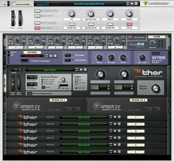
The FM Layers shown from the front inside the Combinator.
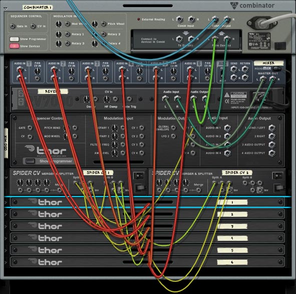
The Thor routings shown at the back of the rack inside the Combinator.

I’ve also included a few other variations on this style of patch in the project files (found at the top of this article). I’m not going to go over all the settings in those patches, as you can open them up and see for yourself. Play around with the settings and you will see that it offers a wide variety of sounds.

That about does it. And now that you have some of these ideas down, have a go at putting together multiple layered Analog, Wavetable, Phase Modulation, or Multi-Oscillator creations, using some of the techniques outlined here. And if you have any great creations that you’ve made or any ideas that you would like to share, I invite you to do so. Leave a comment and let me know what you think.

All my best for now.

40 – Thor Oscillator Wave Mods

In this tutorial I’m going to jump into Thor’s oscillators and show you how a simple method to cycle through the oscillator’s waves (Carriers, Modulators, Phase Mod Waves) can create lots of unexpected outcomes (a la Glitch). It can also allow you to modulate the Oscillators in a way you might not have thought about previously.

In this tutorial I’m going to jump into Thor’s oscillators and show you how a simple method to cycle through the oscillator’s waves (Carriers, Modulators, Phase Mod Waves) can create lots of unexpected outcomes (a la Glitch). It can also allow you to modulate the Oscillators in a way you might not have thought about previously. So let’s jump right in.

The project files can be downloaded here: Glitch-Oscillatoriffic. This zip file contains a single RNS file with 2 different Combinators. You can use the mute buttons on the main mixer to highlight each Combinator and play with each one individually.

I also wanted to say thanks to Geoff Wakefield for talking over this idea through an email exchange. Your ideas are great, as is your music Geoff! Keep up the great work. And go check out his music here: http://soundcloud.com/raven-2741.

First, here’s a video that outlines the basic concepts of modulating Thor’s oscillator waves:

Modulating Thor’s “FM Pair” Oscillator’s Carrier and Modulator

The main trick here is to keep all the devices inside a Combinator so that you can use CV to trigger the Rotaries of the Combinator. The Modulation Bus in the Combinator is used to set up the Oscillator’s Carrier and Modulation waves in the FM Pair, so that when CV is cabled into Rotary 1 & 2, the CV triggers a “cycling” through the different waves. This in turn affects the sound coming out of Thor. You then use the Malstrom’s Mod A & Mod B to supply the CV source, which is sent to the Rotary 1 & 2 CV input.

Also in the Modulation Bus of the Combinator, you’re going to set it up so that Rotary 3 and Rotary 4 (sources) are set up to adjust the Malstrom’s Mod A and Mod B (the destination). You can adjust the Min/Max settings to be as wild and crazy (full 0/31) or as tempered as you like (1/3, for example). In this way, you can not only adjust the Carrier / Modulation waves of Thor’s Oscillator with Rotary 1 and 2, but you can also adjust the Modulation Curve settings of the Malstrom’s Mod A and Mod B with Rotary 3 and 4.

Modulating Thor’s “Phase Modulation” Oscillator’s Wave 1 & 2

Now that we have the basic concept down, it’s a snap to transfer this same idea over to the Phase Modulation Wave 1 and Wave 2. Simply switch the Thor oscillator in slot 1 to “Phase Modulation” and then go back into the Combinator Modulation Bus, and change Rotary 1 and Rotary 2 as follows:

Rotary 1 > Osc 1 Phase Modulation Wave 1

Rotary 2 > Osc 1 Phase Modulation Wave 2

Note: the actual Min/Max settings, as shown earlier, can be anything you like, depending how crazy you like things.

Modulating Thor’s “Wavetable” Oscillator’s Tables

Now instead of the Phase Modulation oscillator, switch to the Wavetable Oscillator. Personally, this is my favorite oscillators for this type of technique. The variety and timbre of the sounds make it a really nice glitch mayhem device for the task. In using it though, there’s only 1 parameter we can effect, which is the actual Wavetables themselves. So switch Rotary 1 in the Combinator Modulation Bus as follows:

Rotary 1 > Osc 1 Wavetable Table

Once again, the actual Min/Max settings are up to personal taste.

One Step Further with the Oscillator’s  “Modulation” Parameter

When it comes to any of these oscillators, there is a “Modulation” parameter that you can also control using CV. For example, when using the FM Pair oscillator, you can have CV control the “FM Amount” knob. When using the Phase Modulation oscillator, you can use CV to control the “PM Amount” knob. When using the Wavetable oscillator, you can use CV to control the “Position” knob.

If you want to do this, you can borrow from one of the existing CV cables coming from the Malstrom and split it using a Spider CV Merger/Splitter, then send one split to the original Rotary destination and send another split into Thor’s CV in. Then it’s a matter of going into Thor’s Modulation Bus Routing Section (MBRS) and entering the following:

CV In1 : 100 > Osc1 FM Amt / Osc1 PM Amt / Osc1 Pos

If you set the FM/PM/Pos on Oscillator 1 very low, then using a high Amount (100) in the MBRS makes sense. If, on the other hand, you set the FM/PM/Pos knob very high, using a lower setting (-100) makes more sense. It depends which direction you want the CV to influence the knob (upward or downward).

Now that we’ve done 3 different Oscillators, I’ll leave you to work your magic on Thor’s  “Multi Oscillator” — yes, you can certainly have a lot of fun with that oscillator as well.

Bringing it all Together

If you look in the project file, you’ll see a few Combinators that take this whole idea a step further by creating a 6:2 Mixer in the Combinator, and then creating three sets of devices (each set contains a different Thor Oscillator, 1 Matrix to use the Mod A/B curves, and an Equalizer at the end of the signal chain, which is then sent to the line mixer and back out to the Combinator’s “From Device” input).

Here’s a video that goes through the steps needed to build one such Combinator:

The idea is a simple one. Have a different oscillator in each of the Thors. Set up the amp envelope any way you see fit. I find a high Decay, Sustain, and Release setting works pretty well, but again, you may have a different preference. The Malstrom Modulation Curves are there for you to use to affect the Thor oscillator waves or even the Modulation knob of the oscillator. This is where experimentation comes in.

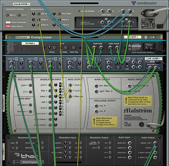
The back of the Rack showing the main components of the Combinator and how the devices are routed.

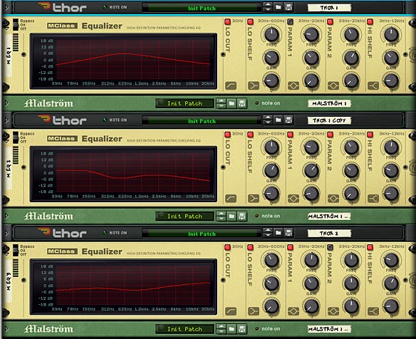
Finally, you have an Equalizer which is applied as a dynamic insert effect used to split each of the Thor sounds into their own specific range along the stereo field. This way, you can set up three oscillators and have each oscillator represent a place along the spectrum: Low, Mid and High. This way, you can balance out the sounds and let them shine in their own frequency range, without interfering with each other. Of course, these are all just suggestions. You might find some other ways to set things up for yourself.

The front of the Combinator, showing all 3 EQ devices to spread out the Oscillator sounds across Low, Mids, and Highs.

I hope this opens up some new creative avenues for you. There’s a lot more that can be done with the Thor oscillators, and this just attempts to scratch the surface or get your feet wet. Don’t be afraid to jump in though, and create your own masterpiece. Oh and if you do, please feel free to share it here. The more we see your ideas, the more we can learn from each other.