Basic Subtractor Patch Pack

Most people that have used Reason since version 1.0 might already be very familiar with the Subtractor. It was the first synth in Reason, and at the time, was the only synth in Reason. However, if you are just coming into Reason right now (version 6.5), you may not have ever used the Subtractor. Or maybe you haven’t touched it in a very long time. So this article will present some of the basic building blocks of Subtractor sounds. Use these 25 patches as starting points for your own creations, or use them as is. What I tried to do here is show some of the capabilities of the Subtractor synth via example patches. There’s no CV, no Combinators. Just straight single Subtractor sounds. As well as some tips for working with this — still amazing — synth.

Basic Subtractor Patch PackMost people that have used Reason since version 1.0 might already be very familiar with the Subtractor. It was the first synth in Reason, and at the time, was the only synth in Reason. However, if you are just coming into Reason right now (version 6.5), you may not have ever used the Subtractor. Or maybe you haven’t touched it in a very long time. So this article will present some of the basic building blocks of Subtractor sounds. Use these 25 patches as starting points for your own creations, or use them as is. What I tried to do here is show some of the capabilities of the Subtractor synth via example patches. There’s no CV, no Combinators. Just straight single Subtractor sounds. As well as some tips for working with this — still amazing — synth.

You can download the patch pack here: Basic-Subtractor. It contains 25 Subtractor patches that are used as examples to show how various basic sounds are generated with the device. Use these as they are, or use them as springboards for your own designs.

So try out the patches, and if you like them please consider donating: [paypal-donation]

The Subtractor is a very straightforward 2-Oscillator synth that is based on subtractive synthesis. It’s modelled to react in the same way an Analogue synthesizer would, even though it’s a digital recreation of one. Its subtractive synthesis engine means that the Oscillators make up the tones, and these tones can be shaped and whittled down between each other, and with mixing and filtering to remove or subtract parts of the sound for a final outcome. Creating sounds is like covering up an entire canvas with a coat of black , and then painting by removing those black areas to reveal the painting underneath. Or rather, painting using the negative space, as opposed to the positive space. This is the basic idea that forms the wealth of sounds you can gleen from the device.

The following shows the Subtractor device, with the “Init Patch” loaded. The Init Patch is used as a starting point for building sounds. Note that the Init Patch does not start at ground zero, and instead is an actual patch that generates an actual sound. I find that in some circumstances you may want to start at ground zero. In this case, you can set all the sliders and knobs to their zero or center position and save the patch. This way, you can always load your new “Init Patch” anytime you like. I’m sure only the die hard sound creation gurus will go to this trouble, but if you are new to any synth, it’s always better to learn from the bottom up, than to have half a sound already generated for you. But that’s just my own opinion.
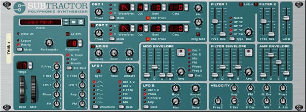
The Subtractor Synth Device
The Subtractor Synth Device. When the device is “Reset” from the context menu, the initialized patch is entered. This is used as a starting point from which you can build your sounds.

The Patches

Following are the various patch examples you will find within the patch pack, along with a brief description and key features of each. The idea behind these patches are to show you the versatility of the synth, and show some of the types of sounds it can produce. Of course, there are many more kinds of sounds. An oboe, bassoon, an ambulance siren, and the list can go on. I encourage you to try your own. But hopefully these can get you started and give you some ideas of how to work with the Subtractor.

  • Bass Example
  • Bass Wobble Example
  • TB303 Example 01
  • TB303 Example 02

These patches are probably the type of sound that is most commonly associated with the Subtractor: Bass. Octave separation between the two oscillators is key here, along with the right kind of filtering and amp envelope.

  • ChipTune Example

This type of sound is one that you’d find on any video game console from the ’80’s. The key to this kind of sound is use of the LFO set to square wave and modifying Oscillator Pitch. This creates the arp feel of the patch. In addition, the Band Pass Filter and setting the envelopes to a full decay and all other envelope parameters to zero gives the sound a minimal 8-bit feel. If you wanted to, you could use the Noise generator to add a little distortion to the sound. But it’s usually better to add a Scream FX unit set to “Digital” damage mode in order to recreate some “crunch” to the sound. Be sure to also keep the Oscillator waves simple as well. Remember, you’re trying to recreate very basic technology here.

  • Filter Sweep Example

This shows you how the Filter Envelope can be used to sweep the filter in your sounds.

  • Flute Example
  • Horn Example

These two patches show you how you can create some wind instruments. One of the keys to recreating these types of sounds is using the sawtooth oscillator and proper filtering. A little modulation helps as well. Generally, I find wind instruments use either Sawtooth or Sine waves, and benefit from a HP filter in Filter 1 and a then the Low Pass filter 2. Some tweaking with the envelopes and a little modulation affecting the pitch to give it a jump in pitch at the beginning can recreate the “blowing” sound that starts at the beginning of these sounds. As with everything in patch design, the devil is in the details.

  • FM Texture Example

Shows how using FM can give a whole new perspective to your sound, and can often generate interesting textures. FM, as well as Ring Mod can make the sound very unnatural, distorted, or even metallic. See the next “Glockenspiel” patch.

  • Glockenspiel Example

This is an example of a glock — or bell-like sound. The use of the Ring Mod feature is what really makes the sound here. The example presented is tonal, because the Oscillators are set one octave apart. But you can get some really interesting atonal bell sounds by separating the Octave in weird degrees (for example, try separating them by 6 or 9 semitones, or play around with odd “Cent” differences).

  • Guitar Example

Guitars are difficult — probably the most difficult — to reproduce. But if you can reproduce a piano sound with a synth, you can take an extra leap to try a Guitar sound as well. The two actually share some similar concepts I think. And while the Subtactor isn’t perfect for guitars, they are still do-able. I found that using Wave 15 in Oscillator 1 paired with a sawtooth provided the raw tones. Then a Bandpass filter 1 going to the Low Pass filter 2 seemed to work out well. I then set the Filter and Amp envelopes to similar values, with medium Decay and Release on both. Keep the Attack at zero to give that initial hard attack. The sustain is tricky, and you can leave it out if you want, or add just a little bit to keep the sound going. That’s your call. The other key to this sound is adding a little FM for a metallic sound. Then turn the Mix knob all the way left so that you’re only hearing the FM Carrier (Oscillator 1). That’s the basis for a typical Subtractor Guitar sound. But play around to see what type of sounds you can build from this technique.

  • Hi Hat Example
  • Kick Drum Example
  • Snare Drum Example
  • Tom Tom Example

These are some Drum examples. While all the drums are different and Subtractor is capable of producing a wide variety of drum sounds, there are some common characteristics. For example, most drum sounds don’t have any Sustain, and also have extremely short Attack — usually set to zero. There is minimal Decay and Release as well. So set up the Amp envelope with this in mind. In addition, your drums may or may not require pitching up or down, so you can disable the keyboard tracking for the Oscillators. Then use the Oscillator tuning to get them to sound accurate (usually in the lower register). This way, the drum will sound at the same pitch no matter where you play it on the keyboard. However, this may or may not be what you want.

Filtering is also important for drums. Generally, Bass, Snare, and Tom drums use Low Pass filtering. While Hi Hats, Crashes, Cymbals, and the like use Hi Pass filtering. The Noise generator can be very helpful here as well. For low Bass Drums, be sure to turn the Color knob closer or all the way left. This brings the register of the noise downward. For more of a biting drum, like a Snare, turn the Color knob closer or all the way to the right.

  • Mod Pad Example

Here’s an example of a Pad – a String Pad actually, which use two Sawtooth Oscillators (great for achieving nice string pad sounds). The idea behind creating a nice Pad sound, in my opinion, lies in two areas: A) The Amp Envelope settings, which are fairly slow. This means that the Attack, Decay, Sustain, and Release are generally pushed up quite high (over a value of 60 in most cases). And B) The modulations you create, which are usually slow as well. This can be anything from the LFO affecting the Mix or Amp, while the Mod Envelope affects the Phase of the Oscillators. The Rates for the LFOs should be set fairly slow (Rate knob more to the left) and the amount values should be subtle (more to the left) as well. This creates very soothing and meandering sounds which work well for Pads.

Of course, never forget that rules are meant to be broken, and nothing here is set in stone. I’m just presenting you with some generalities.

  • Morse Code Example
  • Noise Doppler Example
  • UFO Effect Example

These three show how you can create various special effects with the Subtractor. The Morse Code patch is a good example of how you can use the Random LFO 1 applied to the Filter Frequency in order to create a random Morse Code Sonar sound. Depending what Oscillator you are using and how it’s filtered, you can have it sound like a Telegraph, if you like. So give that a try.

The Noise Doppler Effect is a good example of how you can use the Noise generator on its own, without any Oscillators. The noise is modulated with the two LFOs to create a pseudo-doppler effect. Then the Mod Envelope is used to control Frequency Cutoff on the Low Pass Filter 2. And the Filter Envelope is affecting Filter 1. This all creates a double filter sweep that brings the sound in slowly as it’s sustained. Try playing a chord and note how the sound gets louder over time (as the filters are opened). The LFO 2 plays its part as well by cycling the Amp. A lot of mods working in tandem to affect a very simple Noise generator. Fun stuff!

And finally there is the UFO effect which showcases how you can create some interesting Alien-type sci-fi sounds. As with all the patches here — but moreso in this particular patch, try using the Mod Wheel to show some variation in the sound.

  • Organ Example 01
  • Organ Example 02
  • Piano Example 01
  • Piano Example 02

These four patches are examples of how to recreate organ and piano sounds using the Subtractor. I don’t know about you, but I find programming Pads, Pianos, Organs, and Basses are probably among the easiest types of instruments to reproduce with the Subtractor. I’m not going to go into all the details of how these patches are put together, because they all use different settings, Oscillators, Filters, etc. And you can take a look at them for yourself and then try your hand at creating similar kinds of sounds. I would say that a good starting point is a Sine wave and Low Pass filter though. Sometimes a Notch filter can work well. It all depends. So here are four examples.

  • PWM Lead Example

This shows how the Phase is used to offset and modulate the Oscillator wave, creating “Pulse Width Modulation” (or PWM for short). This is also referred to as “Phase Offset Modulation” (POM). Essentially, its the same thing.

  • Rhythmic Example

In this patch I tried to show how you can get some very complex rhythms using the two LFOs and the Mod Envelope together. The Mod envelope is applied to the pitch to create a sound that continually moves downward. LFO 1 is applied to the Filter 1 Frequency Cutoff to create a gate-like rhythm to the sound. And LFO 2 is applied to the Phase to create a PWM as Phase is swept back and forth. 2 things you can do: A) Try reversing the direction of the sound by inverting the Mod Envelope (click the upside down ADSR graphic button at the top right of the Mod Envelope section). B) Try adjusting the Rates of the LFOs. You can sync them to each other by keeping their rate values identical. You can separate their sync by using two different rates. It’s up to you. But this is different than syncing the LFOs to the tempo of the song; something else you can try out.

Tips for working with the Subtractor

Aside from the basic Oscillators, there are several other wave samples that are hard-coded into the device (represented by waves 5 through 32 in the Oscillator slots). Then there are the usual things that are familiar to most analog synths: 2 filters, 3 envelopes (Amp, Filter, and Mod), 2 LFOs, Noise generator, FM and Ring Modulation, Pitch Bend & Mod Wheels, and a very extensive Velocity parameter section. All of this should be familiar to the synthesist and sound designer, and I’m not going into all the ins and outs here. The Reason User Guide is an excellent resource which goes over most everything you will need to know in order to get familiar with the Subtractor.

What I do want to cover here are a few pointers that may not be obvious when using the Subtractor, or might cause some confusion when you begin to work with it. Think of this as some additional insight into the device which sooner or later you would figure out on your own. Maybe this might save you the trouble?

  • The Subtractor is monaural in two senses: It creates a single channel of sound, and can only generate one sound at one time. However, the device is polyphonic, in that you can play that same sound using multiple keys (think: chords). The number of keys that can be played at the same time is set up in the Polyphony setting (1-99). However, what you may not know is that some of the modulation is polyphonic as well. I know this sounds a little counter-intuitive, but here’s the deal: If you set up your patch to have a Polyphony setting above 2 (usually you want this higher at 8 or 12), then you can use LFO2 to affect the Oscillator 1 & 2 Pitch, Phase, Filter 2 Frequency Cutoff, or Amp. If you do this, playing a broken chord (one note after another) results in an LFO that retriggers separately for each note. This is different than the LFO 1 in the Subtractor, which is a global or monophonic LFO, meaning it does not retrigger with each new note.
  • Using the LFO 2 to affect the Amp is the way in which you set up Tremolo. It’s a shame that you can’t apply this Tremolo to the Mod Wheel inside a Subtractor patch (a fairly common Mod Wheel assignment), however, you can do this if you put the Subtractor inside a Combinator, and assign the Subtractor’s LFO 2 Amount to the Combinator’s Mod Wheel.
  • Those who are new to the Subtractor may not know that in order for FM or Ring Mod to function, you need to have both Oscillators enabled. This is because both of these features rely on the interaction between the two Oscillators. In addition, if you want to hear only the Frequency Modulated sound, without the Modulator, turn the Mix knob fully left. If you want to hear the Ring Mod sound without the Modulator, turn the Mix knob fully right.
  • The Noise generator is also similarly connected to the second Oscillator output, which means turning the Mix knob fully left while the Noise generator is on will reveal nothing from the Noise generator. To hear the Noise generator fully, turn the Mix knob fully right. Therefore, to get a mix between the Noise generator and an Oscillator, turn off Oscillator 2. Instead, set up Oscillator 1, turn on the Noise generator, and keep the Mix knob centered. If you instead want a pure noise sound, keep Oscillator 2 turned off, and turn the Mix knob fully right. This removes Oscillator 1 from the Mix and fully introduces the Noise generator.
  • And as with all rules of thumb, there are always exceptions. If you disable Oscillator 2 and enable the Noise generator, you can still use the FM knob to modulate Oscillator 1 with the Noise generator (remember that the Noise generator outputs where Oscillator 2 is output). You are effectively using the Noise generator as the second Oscillator, and this is used as the Modulator to Frequency Modulate Oscillator 1. So yes, there are exceptions. And while all of this may sound complicated, it’s really not. Think about it. Turn on Noise, increase FM, and turn the Mix knob all the way left. Then experiment with the various Oscillator 1 and Noise generator settings to see what you can come up with.
  • If your Oscillators are set to “o” as opposed to “-” and “x,” then the Phase knobs have no effect on the sound. Phase only works with subtractive (-) and multiplied (x) modes. You can, of course, set up mode combinations where Oscillator 1 is set to subtracive (-) and Oscillator 2 is set to “0.” In this case, only the Oscillator 1 Phase knob will have any impact on the sound.
  • The Velocity section can have an amazing impact on how the sound is played, and has a wide array of options. However, where a lot of new users get confused is in how to set up the Velocity knobs. First things first. Set up a matrix or Thor Step sequencer to play a single note repeatedly at a relatively slow speed, and create a velocity ramp up and down over the duration of the sequence (ramp the full range of the velocity). This sets up the sound to be played at the same pitch, with only the velocity changing as the notes are played. It also helps you to hear what’s going on with velocity. With that done, start experimenting with the 9 velocity knobs to hear how they interact and affect your sound.
  • Another thing to keep in mind when adjusting velocity parameters: When the knobs are dead center, velocity has no effect on the parameters. Turn the knob to the left and velocity has a negative impact on the parameter in question. Turn the knob to the right and the velocity has a positive impact on the parameter in question. In simple terms, if you adjust the Amp velocity in a positive way, the sound becomes louder the harder you play your keyboard (normally what you would expect). However, you can reverse this relationship by adjusting the amp velocity knob in a negative way, so that the sound becomes quieter the harder you play your keyboard.
  • And more about the velocity parameters: Note that if you have a parameter that is adjusted fully one way (for example, the Filter 1 Frequency slider is set to 127 or fully open), then adjust velocity to increase this parameter in the same direction (for example, the Filter Frequency velocity knob is adjusted in a positive direction), the velocity will have no impact on the sound. This is because the Filter Frequency is fully open, and can’t go any further. You could, however, adjust the Filter Frequency in a negative direction in this example, in order to close the filter the harder you play your keyboard.
  • Finally, one last note about the Phase Velocity parameter. Adjusting this will adjust both Oscillator Phase knobs in tandem by the same proportion. This means if you have one Phase knob set to 40 and another Phase knob set to 80, with the Phase Velocity knob set to 10 (positive), when you play the keyboard at full velocity, the Phase knobs will sound as if they are set to 50 and 90, respectively. You can, of course, set up one of the Oscillators to a mode of “o” as outlined earlier, so that the Phase of that Oscillator has no effect on the sound. Of course, this can change the sound. This tandem shifting of Phase is also true of the Phase knob that can be used as a destination for the Mod Wheel. So bear this in mind when adjusting these two parameters.
  • In case you were ever wondering, that second filter in Subtractor is a 12 dB Low Pass Filter, and it cannot be changed to any other Filter Type. Also, when working with it, turning it on will mean that the sound passes through Filter 1 and then into Filter 2 (Serially). With this setting, you can use the Frequency Cutoff sliders of both filters independently (and in some interesting ways — for example, setting up a High Pass Filter 1 and then having it go through the Low Pass Filter 2). Alternately, you can “Link” the Filters together. When they are linked, the Frequency Cutoff of Filter 1 controls the Cutoff of both filters (but the relative position of Filter 2’s Cutoff Slider is maintained). For example, if Filter 2 is set to 50, and Filter 1 is set to 80, moving the Filter 1 Cutoff Slider down to 70 will also reduce the Filter 2 Cutoff to 40. They work in tandem. Note: Low Cutoff Frequencies with High Resonance settings can produce severely loud sounds. This is amplified by the “Link” feature. As such, it’s always a good idea to A) Turn down the Resonance for both filters to zero before applying the “Link” button. And B) Turn down the volume if you are experimenting with the Resonance of either filter while the “Link” button is activated.
  • Filter 2 does have its own dedicated Filter Envelope. Use the Mod Envelope with a destination of “Freq 2.” Now you can control Filter 1 Frequency Cutoff with the Filter Envelope and Filter 2 Frequency Cutoff with the Mod Envelope, all at the same time. This allows you to create some pretty complex filtering in your patches.
  • Lo BW. Unless you are rockin’ out with your PII Pentium 200 Mhz computer from 1994, you will never need to enable this feature. Just pretend it’s not there.
  • Want a fatter sound? If both Oscillators are set to the exact same settings, detune them by a few centos in opposing directions (Oscillator 1 = -4 Cents / Oscillator 2 = +4 Cents). You’ll have to venture outside a simple Subtractor for other fattness tricks, but two of my favorites are A) creating a Unison device under the Subtractor (between the Subtractor and the Mix Channel). This automatically fattens your sound. B) After you have the Subtractor patch set up exactly as you want, duplicate the Subtractor and send both subtractors to separate Mix Channels. Then on the Mixer, pan Subtractor 1 fully left and Subtractor 2 fully right.

So that’s a little bit about the basics of the Subtractor synth, along with a new patch pack. I hope you’ve enjoyed it, and if you have any tips or ideas related to using the Subtractor, please share them. All my best, and happy sound designing!

 

78 – Creating Better Patches (Part 5)

In this fifth installment of my series on better patch design, I thought I would take a much-needed break from all the theory and synth jargon, and instead focus on some creative Thor synth ideas. I can almost hear the collective yawn after reading the last few articles. So let’s spice it up with a few videos that showcase some of the concepts we’ve talked about, but more importantly, let’s just have some fun fiddling around in Thor.

In this fifth installment of my series on better patch design, I thought I would take a much-needed break from all the theory and synth jargon, and instead focus on some creative Thor synth ideas. I can almost hear the collective yawn after reading the last few articles. So let’s spice it up with a few videos that showcase some of the concepts we’ve talked about, but more importantly, let’s just have some fun fiddling around in Thor.

You can download the project files here: better-patches-part5. This zip consists of a few Thor patches and demo .reason files that outline the ideas below. You can use any version of Reason above 4.0 (when the Thor synth was introduced to the world of Reason). Enjoy! Read on for more about these ideas.

The Hoover Sound (Redux)

Chris Petti did a great video on how to create a Hoover Sound in Reason using some Analog Oscillators and a Multi-Oscillator to fatten everything up. If you haven’t seen his video, I’m going to showcase it here. Have a look and build the patch first. We’ll use this as the base building block and figure out a few modifications you can add to enhance it’s flexibility. Here’s his video:

This patch is a really great sound as it is, and Mr. Petti does a bang up job of presenting it to us (not to mention his videos are way cooler than my own DIY camera work). Nonetheless, there’s lots you can do to add to his patch. So I’m going to start where Chris left off and see what we can do to make his patch more flexible, taking it to the next level of patch design. Check out the video below:

Button Trigger Madness

In my never-ending quest to solve interesting problems in Reason, I came across this dilemma. How can I use the button in Thor as a toggle switch to step through the Thor Sequencer? I wasn’t happy with the “it’s not possible” answer. So here’s what I devised. It’s actually a nice simple solution which allows you to use the Thor button as a cycler. The power in this trick is that when the Sequencer is set to “Step” mode, the button can be used to cycle through all 16 steps. If you watch the video below, you’ll see how this can help you devise Thor patches that contain 16 distinct sounds within a single Thor patch.

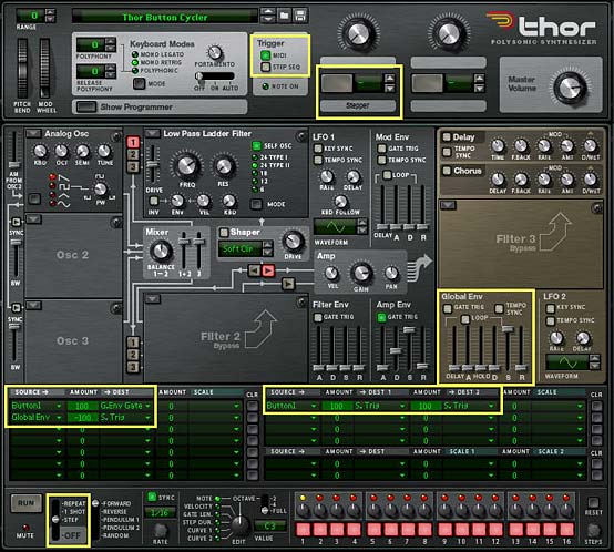
Here’s the short version of how you set it up (see the Chiptune video below for a practical application):

  1. Open a new Reason document. Go into Edit > Preferences, and on the “Audio Tab,” ensure the Sample Rate is set to 44,100 (should be the default). Then close out of this dialog.
  2. Create an initialized Thor device.
  3. Turn off the “Step Sequencer” green light in the Global section’s “Trigger” area. While we’re doing that, label Button 1 the “Stepper.”
  4. Turn off the Global Envelope’s “Gate Trig” green light.
  5. Turn up the Global Envelope’s Sustain to full (0.0 dB), and turn down all other Global Envelope parameters to zero.
  6. In the Modulation Bus Routing Section (MBRS), create the following two lines on the left side:

    Button1 : 100 > G.Env Gate

    Global Env : -100 > S. Trig

  7. Now, enter the following in the MBRS on the first line on the right side

    Button1 : 100 > S. Trig : 100 > S. Trig

  8. In the Step Sequencer section, change the Run Mode to “Step.”
The Thor Button Cycler, showing all the changes that need to be made to the Thor init patch

Now when you press button 1, you’ll notice that the Step sequencer moves forward one step when turned on, and another step when turned off. In essence, we’ve tricked Thor into thinking that both button “on” and button “off” should trigger the Step Sequencer to “Run.” The Global Envelope was required because it is always left on, and so can be manipulated without requiring a Midi Note to “gate” the envelope.

You can now use the Step Sequencer’s Note, Curve 1, Curve 2, Gate Length, etc. to control any aspect of the Thor patch that you like, and build up different sounds at each step of the Step Sequencer. Think of generating 16 different Bass tones or 16 different Pads, Strings, Drum sounds, or any interesting sounds you can dream up. The only limitation is that you won’t have access to the Global Envelope — a minor limitation given the fact that you can get Thor to generate 16 different sounds from a single patch.

Chiptune Sounds (Redux)

As I was experimenting one day, I stumbled upon. . .

. . . a wonderful way to create some Chiptune sounds using the Wavetable Oscillator in Thor and affect it’s “Frequency (FM)” parameter with a stepped LFO. Sometimes it’s not how crazy you can make things. Instead, it’s about keeping things ultra simple. Have a look at the video to see how I paired this Chiptune idea with the above “Button Trigger Madness” idea to create 4 different Chiptune sounds within a single Thor patch.

Here’s the video:

Creating a Sweep

This is an interesting patch that will show you an alternate use for the Velocity performance of the Patch. Since the sweep changes the Volume (along with a few other parameters) over time to sweep the sound upward to full volume, you probably don’t want to have Volume modulated by Velocity. Instead, you can use the Velocity information from the musician’s performance to adjust the speed or rate of the sweep, making it rise slowly when the keys are played softly, and faster when the keys are played harder. You could also set up a button to reverse the Velocity behavior, if you like (see my previous tutorials in this series for explanations on how this is done).

Here’s the video:

Using the FSB for Practice

Another idea I had was to take patches from one synth and transfer them over to another synth within Reason. In this video, I’ll show you how you can take one of my favorite Subtractor patches and recreate the sounds inside Thor. While not every sound from the Subtractor (or Malstrom, for that matter) can be accurately reflected in Thor — they are, for the most part, different synthesis algorithms and techniques underlying each synth — you can still get pretty close, depending on the patch you start out with. It’s good mental exercise. It will help you get to know all the synth parameters and how they work. And you have an endless array of sounds at your fingertips in the FSB.

So why not give this a try with your favorite sounds? And there’s also another reason to transfer patches from the Subtractor into Thor: At the end of the transfer, you’ll still have the Rotaries, Buttons, and step sequencer to enhance or expand on the patches — something the Subtractor lacks. So here’s the video to show you the method I used:


So that’s part five in the series. As always if you have any questions or want to contribute your thoughts and ideas, I encourage you to do so. I’m always interested in hearing new ways you’ve found to work with Reason. All my best until next time.

75 – Creating Better Patches (Part 2)

In this second installment of Reason 101’s Guide to creating better patches, I’m going to focus on Performance, Velocity, and how the MBRS (Modulation Bus Routing Section) in Thor relates to both. The focus is to look at new creative ways you can improve how Thor reacts to your playing style and explain some of the reasons why Thor is such a powerhouse of flexibility in this area. Again, I’m not going to be approaching this as a complete guide to every possible performance technique you can accomplish inside Thor, but rather try to outline its flexibility and show you a few key aspects of performance that you should think about as you develop your own patches.

In this second installment of Reason 101’s Guide to creating better patches, I’m going to focus on Performance, Velocity, and how the MBRS (Modulation Bus Routing Section) in Thor relates to both. The focus is to look at new creative ways you can improve how Thor reacts to your playing style and explain some of the reasons why Thor is such a powerhouse of flexibility in this area. Again, I’m not going to be approaching this as a complete guide to every possible performance technique you can accomplish inside Thor, but rather try to outline its flexibility and show you a few key aspects of performance that you should think about as you develop your own patches.

What is Performance?

Performance has less to do with the actual sound than it does with how the sound is played. If sound is the Motor that moves the car, Performance is the route it takes. It adds dynamism, movement, and modulation. And it is just as important as the actual sound you are hearing, or in our case, “creating” inside Thor. Both the sound and the performance of the sound are intrinsically interconnected. Without performance, sound would be very lifeless and dull, devoid of any movement or humanity. In terms of creating a patch in Thor, there are several performance parameters that you can use to determine how the sound is affected (changed or modulated) based on the way the patch is played by the musician. It is up to you, as a sound designer, to select what changes are made to the sound when a key is struck softly versus when the key is struck hard. It is up to you to determine what happens to the sound when the patch is played at different pitches along the keyboard, or when the Mod Wheel is used. And Thor offers an endless variety of ways you can harness the power of performance.

Performance Parameters

Performance parameters fall into the following categories (note the names in parentheses refer to the different names these performance parameters are given on the front panel of the Thor synth):

  • Velocity (or Vel): How soft/slow or hard/fast the keys on your keyboard are initially pressed.
  • Keyboard Scale (or “KBD,” or “Key Sync” or “KBD Follow”): The Keyboard register/pitch, or, where you play on the length of the keyboard (from -C2 to G8)
  • Aftertouch: Also called “Pressure Sensitivity,” Aftertouch responds to the pressure you place on the keys after they have initially been pressed down.
  • Mod (Modulation) Wheel: A unipolar (0 – 127) wheel that is generally used to (but not limited to) control vibrato (pitch wobble), tremolo (amp wobble), or both.
  • Pitch Bend: A bipolar (-8,192 – 8,191) wheel that is generally used to (but not limited to) control the pitch of the sound upward or downward.
  • Breath: Used with a breath or wind controller. Breathing into the controller will usually cause the sound to be modulated in some way. And if you’re interested in how a breath controller can be used, check out http://www.ewireasonsounds.com/ and http://www.berniekenerson.com/
  • Expression: Usually this parameter is tied to an Expression Pedal, usually found on an organ or piano.
  • Sustain Pedal: Usually this parameter is tied to a Sustain Pedal, usually found on an organ or piano.

Note: While performance relates to how the physical instrument / MIDI Controller is played by the musician, any performance parameter can also be programmed or automated in the Main Sequencer in Reason.

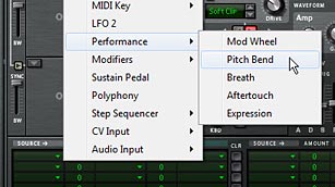
The various Performance parameters that can be assigned in Thor's MBRS.
The various Performance parameters that can be assigned in Thor's MBRS. Note the Sustain Pedal is located in the root folder, not within the Performance subfolder. Velocity is under the "MIDI Key" subfolder, and Keyboard Scale is found at the top of the root menu under the "Voice Key" subfolder.

While all these parameters can be “turned on” or “turned off” (“implemented” or “not implemented”) in a patch, generally you want to make use of most of these parameters in order to make your patches highly flexible and dynamic. However, I don’t use the Breath, Expression, or Sustain Pedal controls. To my mind, these three controls are very specific, and unless the Musician has a pedal or a wind controller (like a MIDI Flute), they won’t be able to make much use of them. If I were designing a ReFill specifically for a Wind Controller, however, then the Breath parameter would be extremely important and you would probably design most of your patches with this type of control in mind. But for the majority, these controls probably won’t need your attention. And I won’t be discussing them here.

Out of the remaining controls, you can break them down into two groups:

A: Keyboard controls: Velocity, Keyboard Scale, and Aftertouch. These are the Performance parameters that rely on how you play the keys on your MIDI keyboard. Velocity and Keyboard Scale are vital in my opinion. Aftertouch is not as vital, since not every MIDI Keyboard controller can utilize Aftertouch. But many CAN utilize it, and as a designer trying to make your patches stand out, this is one area that can separate your patches from others; making them shine. Note: If your keyboard is not equipped with Aftertouch, you can still test your patches by creating an aftertouch automation lane in the Main Sequencer in Reason, and drawing in your automation. This is true of any of the above Performance parameters. However, this kind of testing can be rather tedious. Better to try and purchase a controller that comes equipped with Aftertouch capability if you can spare the money.

B: Wheel controls: Pitch Bend and Mod Wheel. These are the Performance parameters that rely on how you play the two wheels on your MIDI controller. It’s rare you will find a MIDI keyboard that doesn’t have these two control wheels as commonplace controls, so it’s always a good idea to design your patch with these two controls assigned to modulate something in your patch. Furthermore, even if you don’t have a keyboard controller that has these wheels, you can still test the controls by turning the Thor wheels up or down on-screen with your mouse.

Let’s start with the Keyboard controls:

Velocity

Think of a sound that has no velocity sensitivity. You actually don’t need to travel too far to think about it. Load up a Redrum, set the Velocity switch to Medium, and enter a Kick drum that beats on every fourth step (typical four to the floor programming). Now play the pattern back. Sure, the drum sounds great, and it has a beat. But it has no change in level. It’s as lifeless as a bag of hammers.

Now put a high velocity on the second and low velocity on the third drum beats. Listen to the difference. Obviously this is still pretty lifeless, but by introducing Velocity, you’ve introduced a small degree of movement to the pattern. It’s more dynamic “with” velocity than “without” velocity. It doesn’t sound stilted or robotic. It starts to take a better shape. You’ve just added a performance characteristic by changing how the sound is played, albeit, you’re programming the velocity instead of playing it on a keyboard.

Now instead of putting the Kick drum through Redrum, what if you built your own Kick drum in Thor, and played it from your MIDI controller, Your keyboard is capable of a range which goes from 0-127, so you can have 127 different degrees of Velocity (or put another way, you have 127 different velocity levels). When you strike the keyboard to play your Kick drum, the “Velocity” at which you strike the keys can be used to determine the amplitude of your Kick Drum sound.

Velocity in Thor’s MBRS

Now here’s where things get interesting, and Modular / Semi-modular, in Thor terms. Thor offers both hard-wired (fixed) routings, and programmable (adjustable) routings. What you see on the front panel of Thor is what I would term as “Fixed,” while the Modulation Bus Routing Section (the green area below the front panel) offers you the ability to create your own custom routings; not just audio routings, but also performance routings. Using the MBRS, you can adjust what these performance characteristics will affect in an incredibly open-ended way. In other words, you can use any of these performance parameters to change any other Thor parameters you wish (within a few limitations).

Now let’s look at a fundamental use of Velocity in Thor.

Velocity = How soft or hard you play your keyboard. How the note is performed.
Amplitude = The amplitude or volume of a note. How soft or loud the note sounds.

By combining these two parameters together, you end up with the following:

Velocity Amplitude = A change in amplitude when you play your keyboard soft versus hard. Put another way, the “Velocity” is what is “performing the change” while the “amp” is “being changed.” Velocity is the “How” and Amplitude is the “What.” Velocity is the “Verb” and Amplitude is the “Subject.” Or put in Thor terms, Velocity is the “Source” and Amplitude Gain is the “Destination.”

I’m stressing this concept for a very good reason, because it’s the basis of all modulation concepts inside Thor (and any other really good modular synth for that matter). The main reason why people go kookoo for cocoa puffs over the MBRS in Thor is because you can change the “Verbs” and “Subjects” around in any wacky way you like. So any of these “Performance Parameters” can be used to change any other “Thor Parameters.” And not just that, but you can have as many “Verbs” affecting as many “Subjects” as you like. Or have one “Verb” affecting many “Subjects” or have many “Verbs” affecting one “Subject.” The only limitation to how many routings you can create is the number of MBRS rows provided in Thor.

At this point, you might want to know the complete list of Verbs and Subjects right? No problem. In the MBRS, click on the first “Source” field. Those are your “Verbs.” Now click on the first “Destination” field. Those are your “Subjects.”

Typically, you want your Velocity to affect the amplitude in such a way that the softer you press the key, the lower the amplitude is, while the harder you press the key, the higher the amplitude is. But what if we want to reverse this relationship. What if we want softer key strikes to result in louder sounds, and harder key strikes to result in softer sounds. We can very easily accomplish this in Thor using the “Amount” field in the MBRS. Since you can set up the amount to go from -100 to +100, you can make the Velocity affect the Amplitude by a “positive amount” or a “negative amount.” Here’s how both Velocities would look inside the Thor MBRS:

First, turn down the Velocity and Amp Gain knobs on Thor’s front panel, so they are fully left. Then Add the following routing in the first line of Thor’s MBRS:

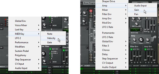
Positive Velocity Amplitude = MIDI Velocity (Source) modulates by +100 (Amount) to affect Amp Gain (Destination)

The Source (MIDI Key > Velocity) and Destination (Amp > Gain) settings in the MBRS row

Next, turn the Amp Gain knob up, fully right. Then change the amount in the MBRS line you previously created, as follows:

Negative Velocity Amplitude = MIDI Velocity (Source) modulates by –100 (Amount) to affect Amp Gain (Destination)

I’m sure by now you’ve noticed that the amount does not necessarily need to be exactly 100 in either direction. You can, of course, enter any amount between -100 and +100 as well. What happens if you lower the Positive Velocity Amplitude? You end up with Velocity affecting the Amp Gain to a lesser degree. In this respect, Amount is actually a way to “Scale” back on the Amp Gain when Velocity is used.

Now what if you want Velocity to affect Amp Gain some of the time, but not all the time? For example, I want to create a patch where the performer can use Velocity some of the time, but not all the time. You can create an on/off switch for this very easily using the “Scale” parameter in the MBRS. Just add the following:

Positive Velocity Amplitude = MIDI Velocity (Source) modulates by +100 (Amount) to affect Amp Gain (Destination)

and this Positive Velocity Amplitude modulation is scaled by +100 (amount) from the Button 1 (Scale) control.

Put another way:

PVA = [MIDI Vel (Source) modulates +100 (Amount) to affect Amp Gain (Destination)] scaled by +100 (Amount) from the Button 1 (Scale) control.

In the grand scheme of things, Sources and Scales are the same. Anything that can be used as a source can also be used to Scale a modulation. The only limitation is that you can’t have a “per voice” parameter scale a “global” modulation. For example, you can’t have the Modulation Envelope Scale the LFO2 Source changing the Global Envelope Attack. Anything that is “per voice” is considered anything in the “black area” on Thor’s front panel, while anything “global” is located in the “brown area” on Thor’s front panel. There’s also a line that separates the “Per Voice” parameters from the “global” parameters in the menu that opens when you click on “Source,” “Destination,” and “Scale” fields in Thor. “Per voice” parameters are located above the separator, while “global” parameters are located below the separator. If you choose a global modulation to scale a per voice modulation, a strikethrough line will appear over the text in the MBRS row.

Now, when Button 1 is turned on (lit up), the Positive Velocity Amplitude is active for the performer. When the Button 1 is turned off, the Positive Velocity Amplitude is inactive. By now, I’m sure you have figured out that you can reverse this “Button 1 on/off behavior” by reversing the Scale amount to -100. This would mean the PVA is active when Button 1 is off, and inactive when Button 1 is on.

You might also want to provide “degrees” or “gradations” of changes in the way the PVA is modulated. If this is the case, change “Button 1” to “Rotary 1” and then use the Rotary to provide 127 shades to how “active” the PVA modulation is. The more the Rotary is turned right, the stronger the effect of the PVA becomes. The lower you turn the Rotary, the less impact PVA will have on the performance. How you set this up is totally up to you, the sound designer.

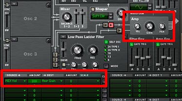
Important Point: Your setting in the MBRS works “in conjunction with” the fixed parameters in the Thor synth. This means that the amount of your Amp Gain knob is going to determine how the routing you’ve set up for it in the MBRS operates. If the Amp Gain knob is set to zero (0) on the front panel, and you’ve set up a Positive Velocity Amplitude as shown above, the knob has no effect, and the MBRS settings are doing all the work to control the Amp Gain. If, on the other hand, you turn up the Amp Gain knob, the sum of the knob’s gain position is added “on top of” the amplitude increase you’ve set up in the MBRS. It is cumulative. This is why you need to adjust the “Amp Gain” knob in the above examples, even when you enter the MBRS settings. The fixed “Amp Gain” knob setting works in conjunction with the adjustable MBRS “Amp Gain” routing assignment.

In this setup, the Amp Gain is completely controlled via the MBRS routing, since both the Amp Gain and Velocity knobs are turned all the way down (fully left).

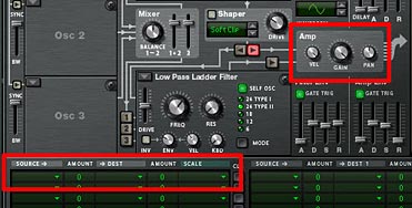
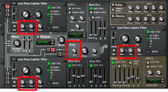
Now that you know a little bit about how the MBRS works, I’m going to completely throw all of the above away, because you don’t have to set any of this up in the MBRS at all. Notice the little “Vel” knob next to the Amp Gain knob? This is an example of one of those “fixed” elements of Thor. And since a “Positive Velocity Amplitude” is such a basic principle in most sounds or patches, The Propellerheads gave it a “fixed” position in Thor, next to the Amp Gain knob. By default, it is turned down or off, but you can raise it (turn it right) to achieve the same effect as if you created a line for it in the MBRS.

In this setup, the Amp Gain knob and Velocity knob are controlling the Velocity, not the MBRS. The velocity control result is exactly the same as in the previous image. It's just a different way to set it up within your patch.

Also keep in mind that since both the “fixed” parameter (the Velocity knob) and routing (the MBRS) work in tandem, if you have the Velocity knob set to 127 (fully right), and have a line in the MBRS set up for Positive Velocity Amplitude as outlined above, you are essentially doubling the degree to which your Velocity is affecting the Amp Gain (+200). Same goes if your Velocity knob is set to zero (0), and you create two lines in the MBRS that both have Velocity affecting the Amp Gain by +100. If you duplicate lines in the MBRS, you ARE going beyond a value of 100, and this is true if you go in a positive or a negative direction. Lastly, if you have the Velocity knob set to +127 and the MBRS is set to -100, then they cancel each other out, and Velocity DOES NOT affect Amp Gain at all.

It should be noted that there are actually three different Velocities that can be used as a Source or a Scale in Thor. Here’s how they differ:

  • Voice Key > Velocity: This setting sources velocity on a “per note” basis. In this respect, it’s the most granular of the Velocity settings in Thor. Each note polyphonically will receive a different Velocity setting based on how soft or hard you play each key. Of course, if you use this setting, you probably also want to be using a polyphonic patch that has more than one voice. Otherwise, it will react the same way as the MIDI Key > Velocity setting.
  • Last Key > Velocity: This allows you to use the Step Sequencer or incoming MIDI key signal to source Velocity. This is also global, so it is also “monophonic” by nature. The idea is that the last key played (from either the Step Sequencer or the MIDI Key) determines how the velocity is sourced.
  • MIDI Key > Velocity: This sources the Velocity globally via the incoming MIDI key signal. It is different from the Voice Key Velocity setting because it is monophonic, and it is different from the Last Key Velocity because it does not react to incoming signals from the Step Sequencer; only incoming MIDI signals (ie: a keyboard controller).

So before you start assigning Velocity settings, think about how your patch will be played by the musician. If your patch is programmed via Thor’s step sequencer, then you will need to use “Last Key Velocity.” If you want Velocity to be accessed via the MIDI Keyboard, all three settings will work, but you have the option to set up velocity on a per-note basis using “Voice Key Velocity” or on a global basis using “Last Key Velocity” or “MIDI Key Velocity.”

Beyond Typical Velocity Settings

Up to this point, all we’ve accomplished is how to create one simple performance parameter in the MBRS which is used the majority of the time in most patches in one way or another: Positive Velocity Amplitude. And yet I can’t tell you how many times I’ve seen patches that don’t even go this far. No, I’m not going to name names. But my point is that if you do anything at all in your patches, at the very least turn up the “Vel” knob next to the Amp Gain at least a little bit. Or keep the Filter envelope and velocity settings at their default in order to create a little movement in your patches that are tied to Velocity. Sure, there are cases where Velocity does not effect Amp Gain, and even cases were Velocity is not used at all. There will always be exceptions. But if you do anything at all, use the velocity knobs that Thor is giving you in the main panel. This will bring your patch designs from Noob to “Beginner” or “Good” as far as Velocity goes. Don’t forget to think about Velocity! It can be of the most expressive of qualities of your patch, and it adds yet another dimension to your patch that shouldn’t be overlooked.

Now if you want to make your patches go from “Good” to “Great” might I suggest getting your feet wet in the MBRS and experimenting with the following ideas:

  1. Change the destination around. What if we have Velocity affect the Filter Cutoff, or the FM Frequency, or the Mix between Oscillator 1 and 2? The point is, try it out for yourself and see what creativity you can come up with. See if it enhances your sound or detracts from it.  Remember that you are not limited to tying volume to velocity.
  2. Test out the “Amount” setting when you are creating an MBRS routing. Sometimes a negative value will produce a better result than a positive one. If a velocity setting produces a very harsh jump in modulation from soft to hard key presses (or vice versa), you might need to scale back the amount to a more comfortable setting.
  3. Try having the Velocity affect more than just a single parameter. Have Velocity affecting both the Filter Cutoff and the Filter Resonance at the same time. Or perhaps, if two filters are used, have the Velocity setting open up one filter (positive amount) and close the other filter (negative amount). This creates something akin to a Filter Crossover.
  4. Try assigning different destinations to the “Voice Key > Velocity” and “MIDI Key > Velocity” sources. I haven’t tried doing this yet, but I would imagine it can create some very interesting Velocity-sensitive sounds, since one is “per voice” and the other is “global.”
  5. Something I’ve been experimenting with lately is having the Velocity affect the Rate of an LFO, and then having the LFO affecting another parameter in Thor. This has the effect of creating a slow modulation on one end of the velocity spectrum and a faster modulation on the other end of the spectrum. Using positive amounts, when you press the key softly, the LFO is slow, and when you press the key hard, the LFO speeds up. Using negative amounts will reverse the process.
  6. Velocity is independent of the Amp Envelope. Whereas the Velocity is a measurement of how soft or hard you press the key (a function of Weight+Speed on the keys), the Amp Envelope is a measurement of loudness over time. That being said, Velocity occurs before the Attack portion of the Amp Envelope, and therefore, it can be used as a source to control the Attack, Decay, or Release portion of the Amp Envelope (or any other envelope) in Thor. Try using Velocity to change these aspects of your patch. It can produce interesting results as well.

So go make some killer patches and practice changing the destinations and the amounts, so that you hone in on just the performance quality you want out of your patch. And ensure that you keep testing using your Keyboard Controller. Play your patches at low velocities and high velocities as you create modulation routings so that you can hear the effect Velocity has on your sound.

Note: Most Keyboard Controllers have built-in velocity sensitivity and even come with specialized settings that allow you to select from different Velocity scales, depending on your playing style. But before you begin, ensure your keyboard IS velocity sensitive. In the rare case that it is not, you can press F4 (in Reason 6) to access the on-screen keyboard. Using the keyboard, you can switch between velocities. It’s time-consuming to test this way, but I would be remiss if I didn’t mention it as an option.

Fixed Velocities in Thor

In Thor, there are essentially two types of “Fixed” Velocities. I’ve already discussed the first fixed velocity as the “Positive Velocity Amplitude” which is otherwise known as the “Vel” knob in the Amp section of Thor. So I won’t go into detail about that. But there’s also another kind of Velocity which is located as a knob on all Filters in Thor. This is what I like to call the “Positive Filter Envelope Velocity” knob. This sets how much the velocity you play on your keyboard affects the envelope of the Filter. Think of it as having Velocity affecting the Envelope. If the envelope is set to zero, the Velocity knob has no effect on the envelope. Nothing happens. If your envelope is turned higher, and Velocity is turned up to 100, for example, the Velocity you play will have a pretty significant effect on whether or not you hear the envelope affecting the filter. Sounds complicated, but test it out by creating a very noticeable Filter envelope, and then turning up both the envelope and velocity knobs, then play your key controller softly and very hard. Notice the difference?

The Fixed Velocity settings in Thor.
The Fixed Velocity settings in Thor. Note that you can turn off these fixed Velocities very easily by turning all the Velocity knobs fully left. This frees you up to set up your own velocity routings in the MBRS, as you see fit.

So that does it for the second part of the series. I’ll continue with the other Performance parameters in part 3. As always, if you have any questions or want to contribute your thoughts and ideas, I encourage you to do so. I’m always interested in hearing new ways you’ve found to work with Reason. All my best until next time.

74 – Creating Better Patches (Part 1)

As a sound designer, your job is to create sounds for others to utilize in their own compositions. There’s immense satisfaction to be gained on both sides as the artist gains access to a myriad of new sounds, and you, as a sound designer, get to benefit from hearing how others are using your sounds (and remuneration for your time and effort creating them is always a plus). So in this article, I’m going to explore some ways you can A) Make your patches more usable by the artist, and B) Think more creatively about the art of patch design.

As a sound designer, your job is to create sounds for others to utilize in their own compositions. There’s immense satisfaction to be gained on both sides as the artist gains access to a myriad of new sounds, and you, as a sound designer, get to benefit from hearing how others are using your sounds (and remuneration for your time and effort creating them is always a plus). So in this article, I’m going to explore some ways you can A) Make your patches more usable by the artist, and B) Think more creatively about the art of patch design.

You can download the project files here: zero-initialized-patch-files. This zip file contains the Reason 6 setup for creating a Thor patch. It also includes a few fully initialized patches for the various Reason devices. These patches, as explained in the tutorial below, can be used as a starting point to create a basic patch in all three of the Reason synths. The patches are used to force every parameter to “zero” or “off” so that you can truly start the patch creation process from a completely blank slate. To this day, I still use this method when starting a new sound or patch design. It may take a little longer to set up. But it ensures I’m not colored by any settings that are already input into the device, and ensures I think about the whole audio signal as I go.

This article is not about every single patch design possibility. You could literally write several books on the subject and still not be finished. Instead I’m going to focus on a few key areas that are important and may open you up to some new sound design possibilities. For this series of tutorials, I’m going to focus on Thor, and show you some of its flexibility. Being the flagship synth of the Reason software, it deserves more attention than the other synths. It also has a steeper learning curve than the other synths (not to say the other synths aren’t very powerful. They are! But Thor is just so much more flexible in a lot of ways, mainly due to it’s semi-modular design).

I’m also going to assume that you know a little bit about what an Oscillator, Envelope and Filter does, and you’ve worked a little bit creating your own sounds. If you’re unfamiliar with these basic synth concepts, then start off reading the Reason Manual (start with the Subtractor section), or else go online to Wikipedia and get familiar with the basic building blocks of sound and sound modulation. Then come back and see if this makes a little more sense to you.

Also please take this series of articles with a grain of salt. Sound design is very subjective and encompasses a wide range of styles, approaches, likes and dislikes. This is not gospel. This is just some of the ways I go about creating my patches. You may have your own methods which are just as valid as mine. There’s no right or wrong (except that you don’t want any patches to clip or have a volume that’s too hot – this is pretty much golden no matter who you are).

The Checklist

Before jumping into some of the basics, here is a checklist you can use to ensure you make the most out of your patches and sound designs. This breaks everything down into a few important sections. When I’m designing a sound, I’m always conscious of the following:

  • What sound are you creating (optional): Sometimes you want to get in there and create a Bass, other times, you just want to experiment and see what you come up with, without having a preset notion of the end sound design. Both approaches should be explored, and is totally up to you.
  • Amplitude: Ensure the patch is in the general range of -6 dB when the big meter is set to peak / peak mode. Never let the patch clip (go into the red).
  • Performance Assignments: Ensure that rotaries, buttons, and wheels have assignments. Brownie points for Velocity, Aftertouch, and Key Scaling (if needed). Provide the most functionality or flexibility you can for the user in each and every patch.
  • Labels: Ensure all the rotaries, buttons, patch names, and ReFill Folder names and structure, are logical, useful, or make sense. Bonus points if you can make the labels have meaning both on a functional level (what I call the “engineering”) level, and on a descriptive level (what I call the “Plain English” or “Layman’s terms”) level. For example, the label “LP Filter” is functional. The label “Brightness” is descriptive. So perhaps you can combine them and call the label “LP Brightness,” which can make it a more useful label. Remember when you are creating patches for others to use, the label is often the only documentation provided with a patch. So make it count.
  • Documentation: You may find that a patch you create requires some user documentation. Situations where this can come in handy is if you want to further explain the interaction between rotaries/buttons, how to use the Mod Wheel or Performance during play, if a patch is designed for a specific key range and what that range is. Providing extra documentation can help make you go from a good patch designer to a great patch designer (even if the majority don’t read the documentation). That being said, in general you should always try to design your patches to have the most flexibility possible. And documentation is no substitution for intuitive patch design. The more intuitive and interesting you can make your patches, to the point where anyone who opens them can start playing and use them without documentation, the further along the road to “great” patch designer you are.
  • Creativity: No, there’s nothing under the sun that hasn’t been done before. True. But be creative. Try out new methods and think outside the box. How about applying the rate of an LFO to the Velocity, or adding FM between two oscillators to the Aftertouch setting? What about changing Delay Feedback at the same time you open up the Filter Frequency and attaching that to a Rotary? There’s a million different approaches, combinations, and ideas. Do something that sets your patches apart from everyone else.
  • Did you create the sound you wanted? Is there anything you would change to make it better? This is the final stage where you review the sound and ensure that everything makes sense, and that things sound the way you want them to sound. Often times, I’ll put down the patch or else create a series of patches and then leave them alone for a few days, and then come back and listen to them again. Often times this can shed light on a few areas that could be tweaked or rewritten to make the sounds better. I might change assignments from the Mod Wheel to aftertouch or velocity. I might find a sound is too harsh, so I’ll filter it a little more. This is where you put the finishing touches on your patches, just as you would perform final EQ adjustments to your songs.

Amplitude & The Big Meter

First, let’s start with the Level / Amplitude of your patch. While I know everyone has their own opinion on what the “correct” level of a patch should be, unless I’m designing something solely for myself, and solely for a specific reason, I generally open up the Big Meter in Reason’s Hardware Interface, set it to VU+PEAK mode, and ensure the levels of your patch do not exceed approximately -4 dBFS (VU) or -6 dBFS (Peak). This is dependent on a lot of factors of course, and the meters are only an aid to help you. They are not meant to replace your ears. If the patch sounds right, then it IS right. But one thing is for sure: you don’t want the meters going in the red. EVER! This means your signal is clipping, and should be avoided. Better to be too cautious than too aggressive in your sounds.

Note that clipping occurs when you see the Meter go into the red. With Reason’s default settings, this is a value of 0 dBFS (VU) or 0 dBFS (PEAK). Ensure that your audio signal is always consistently below these values, no matter what performance parameters are used in the patch, and no matter what combination of these performance parameters are used (more on this below).

If you’ve never worked with meters before, it helps to understand how they work and what they are telling you. Without getting bogged down in the theory behind them, here’s the bare bones of what you need to know. First, the video:

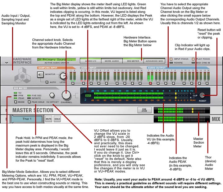
Next, the quick discussion: All 3 meters are explaining the same thing, but in different ways. The VU (Volume Unit) meter is averaging a period of time, and so provides you with an average volume level for what you’re monitoring. The PEAK meter, on the other hand, is providing you with an instantaneous Peak level for what you’re monitoring. It may seem from reading this that the VU meter isn’t accurate for measuring clipping, but this is not entirely true. While PEAK is a better indication of the actual highest point of your audio level, the VU meter is closer to what the human ear perceives as loudness. Therefore, it has value when creating your patches. For example, you may have a sound without a loud peak, but with a very loud average volume (for example, long sustained pad sounds). This can lead to a patch that seems too loud when you hear it, but still doesn’t clip. Or you may have a sound that has very high peaks, but seems too soft to your ears (vocals and transients can easily fall into this category). These two meters can help guide you to see that you’re on the right path. The following explores the way the Big Meter operates in Reason (the down and dirty “Coles Notes” version):

The Big Meter and its associated parameters.

Here’s a quick tutorial to set up the Big Meter to monitor your patch sound designs:

  1. First, click on the Audio I/O and Big Meter buttons in the Hardware Interface. This opens both, and expands the Big Meter below the Audio I/O.
  2. Next, click the little square below Audio Output 1/2 (or whichever audio output you want to monitor). Alternately, use the Big Meter Channel knob to turn the Big Meter’s focus on the proper output.
  3. Using the Big Meter Mode button, adjust until you have VU+PEAK mode selected. Now you can monitor your audio using both meters. VU is listed in light blue along the top of the Big Meter scale, and PEAK is listed in orange along the bottom. When viewing the audio output LED lights on the Big Mixer, note that the VU LEDs are always to the left of the PEAK indicators. And the Peak indicators are displayed as two LED lights to the farthest right. It takes a little getting used to, but it’s a valuable way to monitor your sound and ensure there is no clipping.
  4. Ensure the Peak Hold is set to Five Sec (to indicate that the PEAK setting readjusts after every 5 seconds).

In addition, setting the amplitude of your patch revolves around several interrelated aspects of your patch: The big Volume knob, How many Oscillators are being used, the Polyphony setting, how they are routed, the Mix between them, The Decay / Sustain setting of the Amp Envelope, the Gain setting of the Amp section, the Filter Drive settings, and even the Filter Frequency and Resonance. All of these factor into how loud your patch sounds, and whether or not it’s clipping. In fact, everything you do in your patch will affect the amplitude one way or another. That’s just the nature of the beast.

Generally speaking, I adjust most of the amplitude levels during patch creation; as I go, since most changes you make to a patch will affect amplitude in some way. So I’m forever adjusting and tweaking the levels as I create the patch. However, I tend to work from the inside out. I’ll adjust patch settings inside the Voice and Global sections of Thor first, making sure those settings are correct. Then I may make an adjustment to the main level of the Thor patch via the big Volume knob after the patch settings are in place. In addition, I usually (but not always) work by following the signal flow. For instance, I’ll first adjust the drive setting of Filter 1 before adjusting the Gain setting of the Amp section inside Thor. This helps to get the levels correct, and also helps to understand the signal flow of the patch you’re creating.

Testing Amplitude During Performance

I categorize the Polyphony, Envelopes, Velocity, Aftertouch, and Key Scaling settings in this group of volume control. I generally know in advance if I’m going to be creating a patch that is monophonic versus Polyphonic. And if the patch is monophonic, I set the volume levels while playing a single note at maximum velocity. If the patch is polyphonic, I’ll adjust amplitude settings based on playing a 3- or 4-key chord at maximum velocity. It’s also important to play the patch up at high registers and down at lower registers to see if the volume is consistent across the entire keyboard. Often times, a synth that has a proper volume in the C2 and C3 range, can be overly bright at higher registers (which can increase the volume), or can overload the bottom end amplification-wise. Without getting too deep into this conversation, just keep in mind that the number of voices (polyphony) affects amplitude, and should be tested accordingly.

The envelopes you set up for the Oscillators are also important. The sound can start off low, and then build up over time to peak much higher than your maximum. So if you’re creating a long drawn-out pad sound which develops over time, be sure to listen and monitor the sound played over the entire duration of the envelope and check that big meter to make sure you don’t go too high.

And not to make things even MORE complicated, but if you have set up your rotaries, buttons, mod wheel, aftertouch, and velocity settings to certain parameters, it’s very important that you test out all the possible combinations of these buttons and performance settings and see how they all interact together. Often times, when you create a patch, you’ll test out the sound while turning Rotary 1 front and back, but have you tested how Rotary 1 sounds when Rotary 2 is turned front to back as well? Or when button 1 is on, etc. You can easily end up in situations where Rotary 1 sounds perfect on it’s own, but introduce Rotary 2 and all of a sudden the patch is clipping. So be very cautious of that.

It’s important to understand that all of these settings inside Thor affect the amplitude and are interconnected, playing off each other. Balancing out the amplitude while getting the sound you want is one of the primary keys of good sound design. So when you’re first starting out, don’t be afraid to push the limits and see how turning up the filter drive affects the sound, or turning down the gain while turning up the Filter 3 drive changes the sound. But be cautious about good balance. Generally if you turn up one amplitude setting, this will mean you have to turn down another setting somewhere along the audio signal chain. This is where the Big Meter can help you understand how the various parameters you set affect the amplitude. After a while, you may find you don’t need it at all.

Volume Consistency

There’s also one other reason to pay close attention to the volume level of your patches: Consistency. You don’t want one patch to be extremely loud and the other patch to be extremely soft. You want to provide some degree of consistency across your patches, and indeed your Refill.

For me, a good consistency is when the patches are all somewhat close to each other in volume, both average volume and without causing any peaks to clip. Of course, this will also depend on the type of instrument you’re creating, the frequency range of the instrument, the rise and fall of the Amp Envelope, etc. But you still want them all to be somewhat consistent relative to each other.  Make it easy for the user to use your patches. Providing consistency will help do this.

Note: A good test to see how accurate your ears are is to turn off the big meter entirely, and hide all the metering (put a piece of tape over the metering displays on your monitor if you have to). Design a few different patches in Thor without the aid of any metering. Then go back through the patches and see how close you came to getting the patches all set to consistent levels.

In summary, it’s a good idea to think of Volume and amplitude in your patches as a system of pulleys and levers that need to equalize at the outcome. If you pull one lever up, you generally need to pull another level somewhere in the audio chain down. Kind of like balancing a budget. If you spend more in one area, you have to save in another. Thinking in these terms will help you come out with a better patch in the end, which is consistent with your other patches. When you produce a refill, getting the levels even across the board is very important, and it’s something that will make your ReFills better in the long run. So take a minute to explore how volume is affected when you change things around in your patch, and learn to compensate when you raise that drive on that filter.

Setting up your Thor patch

Now that we’ve got the basics out of the way, let’s fast forward to looking at how you can assign some parameters in Thor. What I tend to do when starting any new patch is to “zero out” all the parameters. This means I don’t start from the typical “Init patch” assigned to the device. Instead, I’ve created my own set of “True Init Patches” for each of the devices. This means all the sliders and levers are dropped to zero, all the buttons are turned off, and there are no assignments anywhere. I do tend to leave the polyphony setting to “1” voice for “polyphony” and “1” voice for “release polyphony” — I can always add more voices later. Furthermore, I remove all the labels for the rotaries and buttons. Starting from this blank slate is worthwhile for two reasons:

  1. Starting from “zero” does not influence the direction I am headed when creating a sound or patch. With the typical “init patch” setting in Thor, for example, I might be influenced to create a sound which uses an analog oscillator and low-pass filter, and keep the settings for the envelopes as they are. If, on the other hand, you start out with a completely blank slate, there is nothing that is previously set to color the direction of your patch creation. This may not be your style, but I find it very refreshing to start with a blank piece of paper when writing something, as opposed to starting somewhere midway in the story, where the introduction has already been written.
  2. Second, if you are new to synthesizers and sound design, starting from ground zero forces you to learn what each setting does. And it forces you to learn one step at a time. You’ll soon learn that without an Oscillator and Amp envelope turned on in Thor, you won’t hear a sound. But forcing you to turn it on will force your brain to make the connection by showing you what the Amp envelope is doing with your sound. Same for each and every parameter in Thor or any other synth for that matter. Once you become more comfortable with all the settings, it’s perfectly fine to create your own “Init Patch” or use the one that Reason comes with. But for the sake of learning your synth from the ground up, there’s no better exercise than to turn everything off and start from nothing. You may stumble a bit at first, but you’ll learn much more in the process I think.

That’s all I have for you in this tutorial. In the next part, I’ll go into more depth on ways you can use Thor creatively to produce some interesting results in your patches. I’ll try to think along a few lines that you may not have thought about before, and give you a few ideas that can take your patches from “good” to “great.” Until next time, get familiar with these concepts of volume, metering, consistency across your patches, and the basics of starting from the ground up. Then continue this journey to better sound designs and better patches in Reason. Happy music-making!

And please, if you have any comments, ideas, thoughts about these topics, please let me know. I”m happy to receive feedback and I’ll do my best to help answer any questions you might have.