57 – Kong FX Chain Builder

In this tutorial I’m going to show you how to create a flexible FX chain that has 8 stops along the chain, and at each of these stops, allows you to select from 1 of 6 different FX devices. This means you have a total of 48 different FX devices to select from in the chain, and the possible permutations of all these FX are 8×7 possible FX combinations, which amounts to 40,320 possible FX chain permutations.

In this tutorial I’m going to show you how to create a flexible FX chain that has 8 stops along the chain, and at each of these stops, allows you to select from 1 of 6 different FX devices. This means you have a total of 48 different FX devices to select from in the chain, and the possible permutations of all these FX are 8×7 possible FX combinations, which amounts to 40,320 possible FX chain permutations. Don’t believe me? Go here: http://www.vpgenius.com/tools/combin.aspx. That’s a hell of a lot of possibilities. Now change the order of your FX chains, and you end up with double, triple and even more possibilities. So let’s see how it’s all done.

You can download the project files here: Kong-FX-Chain-Builders. The file contains 3 different FX chain combinators that are outlined below. The effects in each chain are the same. The only difference is that they each present the chain in a different order. You can take this idea and build any number of effects chains in any order you wish to combine both “Serial” and “Parallel” processing of your audio signal through various FX that you create in Reason. It’s all only limited by your own imagination.

Introducing the “Kong FX Chain Builder” Patch

The beauty of this type of system lies also in the fact that you can combine a “Serial” and “Parallel” audio system together. So when I was working on my “Key Flux FX Processor” in project number 56 here on my site, I introduced the notion of a Parallel system, whereby the same audio was sent through many different FX chains and then sent out to the soundcard. In this tutorial, I’m going to introduce the idea of a Serial FX system, and merge it with a Parallel FX system so that you get much more flexible audio routing and audio possibilities.
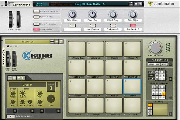
The main controls for the Kong FX Chain Builder (and Combinator Controls)

The idea is pretty simple. First you have a set of FX in a chain, as follows:

Filter > Delay > Distortion > Chorus > Phaser > Delay 2 > Filter 2 > Reverb

Now, each of these “stops” along the chain also has 7 different selectable FX sound possibilities, as follows:

Filter>

(Pad 1)

Delay>

(Pad 2)

Distortion>

(Pad 3)

Chorus>

(Pad 4)

Phaser>

(Pad 5)

Delay2>

(Pad 6)

Filter2>

(Pad 7)

Reverb>

(Pad 8 )

FX 1 FX 1 FX 1 FX 1 FX 1 FX 1 FX 1 FX 1
FX 2 FX 2 FX 2 FX 2 FX 2 FX 2 FX 2 FX 2
FX 3 FX 3 FX 3 FX 3 FX 3 FX 3 FX 3 FX 3
FX 4 FX 4 FX 4 FX 4 FX 4 FX 4 FX 4 FX 4
FX 5 FX 5 FX 5 FX 5 FX 5 FX 5 FX 5 FX 5
FX 6 FX 6 FX 6 FX 6 FX 6 FX 6 FX 6 FX 6
Dry Audio Dry Audio Dry Audio Dry Audio Dry Audio Dry Audio Dry Audio Dry Audio


The Dry audio is there so that you have a selection that sets things back to being the original audio, like a pass-through. Using this table you can come up with an amazingly large array of different sounds by mixing and matching the different FX together. You can, for instance, create the following:

Filter >

(Pad 1)

Delay >

(Pad 2)

Distortion >

(Pad 3)

Chorus >

(Pad 4)

Phaser >

(Pad 5)

Delay 2 >

(Pad 6)

Filter 2 >

(Pad 7)

Reverb >

(Pad 8 )

FX 1 FX 1 FX 1 FX 1 FX 1 FX 1 FX 1 FX 1
FX 2 FX 2 FX 2 FX 2 FX 2 FX 2 FX 2 FX 2
FX 3 FX 3 FX 3 FX 3 FX 3 FX 3 FX 3 FX 3
FX 4 FX 4 FX 4 FX 4 FX 4 FX 4 FX 4 FX 4
FX 5 FX 5 FX 5 FX 5 FX 5 FX 5 FX 5 FX 5
FX 6 FX 6 FX 6 FX 6 FX 6 FX 6 FX 6 FX 6
Dry Audio Dry Audio Dry Audio Dry Audio Dry Audio Dry Audio Dry Audio Dry Audio


And that is just one example.

Switching the Order of Effects in the Chain

The Kong FX Chain builder from the back of the rack

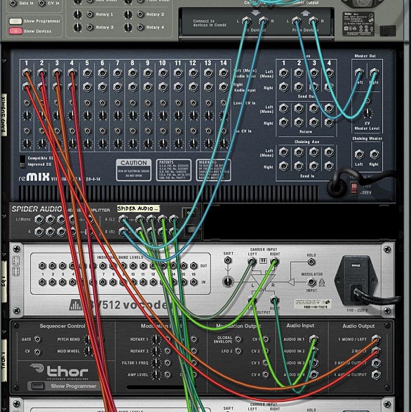
Now I know some of you are going to say, “well why can’t I switch the order of the FX chain?” So instead of having the Filter come before the Delay, how about switching it so that the Filter comes after the delay. And to that I’ll say that Reason is not the easiest software to work with when it comes to making routing decisions such as these and building it into a single setup is very difficult. But thankfully it’s pretty easy to build multiple instances of the Combinator to come up with any FX chain order you like. The trick is to flip to the back of the rack and change the following:

  1. The order of the “Gate Out” CVs from the first 8 Kong Pads
  2. The order of the 14:2 Submixers and their associated splitters. The signal flow goes from the “To Devices” of the Combinator into the first Effect’s splitter. Then the 14:2 Submix main output of the first effect goes into the second effect’s splitter. And so on down the chain, until the final output goes into the Pan splitter device. The Pan also has a bank of different “Global” LFO Panning selections. This can be selected on Pad 15.

So anyway, this just shows you that with a little thought, you can create a variety of FX of your own and route them in a serial way. Then use the “Parallel” processing idea to create multiple effects at each stop in the chain. Simple enough right?

Here are the other 2 effect chains I came up with. Feel free to create your own based on variations that work for you. You can either change the routing scheme as I outlined above, or you can change the actual effects at each stop. As you can see, you don’t even need to have all the FX in play within the chain. You can keep any part of the chain set to “Dry Audio” so that it will not be affecting the chain at all. This means you can make your chain simple with only 1 effect in play, all 8 in play, or any amount in between. Here are the other two effect chains I put together:

Delay > Filter > Phaser > Delay 2 > Chorus > Filter 2 > Reverb > Distortion

Phaser > Chorus > Filter > Reverb > Distortion > Delay > Delay 2 > Filter 2

Working with the “Kong FX Chain Builder”

There are 2 components to working with the Kong FX Chain Builder: 1. The Combinator and 2. The Kong device. Both work together to create your FX chain. You can also use them “Live” and play the different effects out on the pads in real-time, or else build them up in the studio until you find a combination of effects that works for your sound, and then just leave this setting as it is (or save it for future recall).

I’ll start off with the Kong device. Note that if you want to fully utilize the device, you should create a track for it in Reason or Record’s Main Sequencer. This way, you can not only play the Kong device, but also record your Kong pad changes over time. And you can also lock your pad control surface to the Kong device and another controller to the Combinator; essentially controlling them both via 2 different controllers at the same time. So here are all the Kong pad settings:

  • Pads 1 to 8: These are the 8 stops in the FX chain going from Pad 1 > 2 > 3 > 4 > 5 > 6 > 7 > 8. In the original file I created (Kong FX Chain Builder A), this goes from Filter > Delay > Distortion > Chorus > Phaser > Delay 2 > Filter 2 > Reverb. The Pads act as a cycle, starting with a dry signal, then going through 6 different possible FX. The pad cycles through these 7 positions. So each time the pad is pressed, you’ll hear a new effect inserted into the chain.
  • Pads 9 and 10: Decay Down / Decay Up – These pads will shift the decay of all the Reverb effects upward or downward. So you need to have the Reverb effect turned on (in other words, you need to have one of the 6 Reverbs enabled; not the dry signal).
    Note that there is an upper and lower limit, which, when reached, will not go any further. However, the pad can continue to go upward or downward for a few more times. This means that if you push the decay all the way to zero, and still hit the “Decay Down” pad, it will continue to move downward. So it may take a few more Pad pushes on the “Decay Up” pad to get it back to a “zero” postion (until you start hearing the decay again). This is true of all the Up/Down pads.
  • Pads 11 and 12: Envelope Pattern Down / Envelope Pattern Up – These pads will shift the matrix pattern banks upward or downward. These curve patterns are used to “play” the envelope amount on all the filters in the system. Therefore, you need to have at least one filter turned on to hear anything. You also need to have the “Env Pattern On” button (button 2 on the Combinator) enabled. There are 25 patterns on each Matrix (from A1 to D1), for a total of 50 patterns from which to select (you need to use Button 4 on the Combinator to switch between Matrix A and Matrix B).
    Note that there is an upper and lower limit, which, when reached, will not go any further. However, the pad can continue to go upward or downward for a few more times. This means that if you push the patterns all the way down to A1 on the Matrix, and still hit the “Env Pat Down” pad, it will continue to move downward. So it may take a few more Pad pushes on the “Env Pat Up” pad to get it back to the “A1” postion (and get the patterns to start moving forward again). This is true of all the Up/Down pads.
  • Pads 13 and 14: Volume Down / Volume Up – These pads will shift the global volume upward or downward. Note that there is an upper and lower limit, which, when reached, will not go any further. However, the pad can continue to go upward or downward for a few more times. This means that if you push the volume all the way down to zero, and still hit the “Volume Down” pad, it will continue to move downward. So it may take a few more Pad pushes on the “Volume Up” pad to get it back to a “zero” postion (until you start hearing the volume again). This is true of all the Up/Down pads.
  • Pad 15: Panning. You can select from 6 different Auto-panning effects, which are global and affect the signal after it has gone through all 8 effect stops in the chain. There is also a seventh “dry” position, which is on by default. The Pad cycles through all 7 positions (6 “auto-panners” and 1 “dry” position).
  • Pad 16: FX / Bypass – this allows you to switch between hearing the effects chain or hearing the original “dry” signal.

The Combinator controls are outlined below:

  • Pitch Bend: Not assigned.
  • Mod Wheel: Controls the envelope amount on all the filters. This is used in conjunction with the Envelope patterns in both Matrixes that also control the envelope amount. In other words, you can use the Mod Wheel to scale the envelope amount, and therefore, how much the envelope is affected by the patterns or not. If you wish to control the envelope amount without having any patterns control the envelope, disable button 3 on the Combinator, and then use the Mod Wheel, which will now be the only parameter affecting the amount of envelope applied to the filter(s).
    Note also that both the Mod Wheel and the Patterns affect all filter envelopes globally; both “Filter 1” and “Filter 2.” And of course, at least one filter needs to be added into the FX chain for you to hear the effect of the Mod Wheel or Patterns applied to the Filter Envelope amount.
  • Rotary 1: Filter 1 Frequency. Adjusts the Frequency of the first filter in the chain. All the filter selections for “Filter 1” are affected using this rotary, so that as long as you have one of the six filters enabled in the Filter 1 slot, the Frequency can be adjusted.
  • Rotary 2: Filter 1 Resonance. Adjusts the Resonance of the first filter in the chain. All the filter selections for “Filter 1” are affected using this rotary, so that as long as you have one of the six filters enabled in the Filter 1 slot, the Resonance can be adjusted.
  • Rotary 3: Filter 2 Frequency. Adjusts the Frequency of the second filter in the chain. All the filter selections for “Filter 2” are affected using this rotary, so that as long as you have one of the six filters enabled in the Filter 2 slot, the Frequency can be adjusted.
  • Rotary 4: Filter 2 Resonance. Adjusts the Resonance of the second filter in the chain. All the filter selections for “Filter 2” are affected using this rotary, so that as long as you have one of the six filters enabled in the Filter 2 slot, the Resonance can be adjusted.
  • Button 1: Not Assigned.
  • Button 2: Invert Envelope. This is a simple envelope invert button, and affects all filters in both the “Filter 1” and “Filter 2” slots in the FX chain.
  • Button 3: Envelope Pattern On. This turns on the envelope pattern Matrixes so that the curve pattern that is selected in Matrix A or B will affect the envelope amount of all Filters in both “Filter 1” and “Filter 2” slots in the FX chain. There are 2 parameters that both affect the Filter Envelope Amount: The pattern here, and the Mod Wheel. The higher you raise the Mod Wheel, the higher the Envelope amount. You can use a combination of the pattern and Mod Wheel to effectively “play” with the Filter Envelope Amount parameter. The reason I set it up this way is that you have ultimate control over the envelope amount. For example, you can turn off the pattern by keeping this button (button 3) disabled. Then use the Mod Wheel to scale the amount upward or leave it fully off (when the Mod Wheel is fully down). Or you can turn on the pattern and leave the mod wheel fully down to have the amount controlled solely by the pattern. Or use both in combination to play around with the envelope amount.
  • Button 4: Envelope Bank A / B. Selects between the two pattern banks (2 Matrixes) that affect the Envelope Amount parameter on all filters (read above for more information). There are 25 patterns on each Matrix (from A1 to D1), for a total of 50 patterns from which to select. Button four switches between the first 25 patterns on Matrix A (when the button is disabled) to the second set of 25 patterns on Matrix B (when the button is enabled).

Visualizing the active FX Chain

Sterioevo over at  Mute.Hate.Loud.Love was kind enough to provide two methods for visualizing the active effect chain (see the comments below this post for more info about this CV method). He used the Gate Length of the Thor Trigger devices to change the Modulation Level Bands of the BV512 Vocoder and the delay steps in the DDL delay devices to show visually which effect was enabled at each stop in the FX chain. So I updated the patches (just download the Project files again if you haven’t already) using his “Vocoder Visualization” method. You’ll now see a Vocoder under the main Kong device. This uses an 8-band setting to display the position of each effect on Pads 1-8 in the Kong device. This way you can visualize what’s going on as you play the pads. Very cool and handy little tool! Thanks Steve!
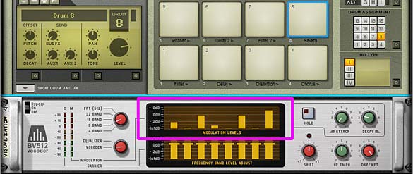
Visualizing the active FX chain using the Modulation Levels of the BV512 Vocoder

So what do you think of this combination of “Parallel” and “Serial” effects processing using Kong? Any other ideas come to mind on how these ideas can be used? I can envision setting both this and the “Key Flux FX Processor” ideas on the alternate devices. For example, you could set up the “Key Flux FX Processor” on Kong and you can probably set up the “FX Chain Builder” on a Combinator. The device is somewhat irrelevant. What matters is the concepts and what you want to accomplish. And as you can see, Reason can usually provide an avenue to make your systems come to life.

Until next time, hope you can make this work for you and use it in your own productions. If you do, drop me a line and let me see what you come up with. I’m always interested to see how others’ use my patches. Cheers for now.

BV512 Spectrum Analyzer

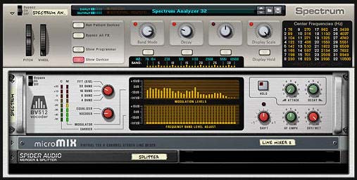
This is what fills my heart with warm fuzzies. When those that are part of the Reason and Record community come together to Analyze and tackle some of the more difficult aspects of the software and fill in the gaps that may be left by incomplete specifications. Wendy Dunham and Giles Reaves have teamed up to provide the penultimate BV512 Vocoder Spectrum Analyzer for Reason and Record.

This is what fills my heart with warm fuzzies. When those that are part of the Reason and Record community come together to Analyze and tackle some of the more difficult aspects of the software and fill in the gaps that may be left by incomplete specifications. Ed did it previously with his Thor Sine Wave Shaper tutorial, using it to cross-fade between 4 different devices. And now Allen Day (“rogerraa”), Wendy of Wendy Dunham Music fame and Giles Reaves (Selig) from the Selig B3-Leslie refill fame have teamed up to provide the penultimate BV512  Spectrum Analyzer. Selig provided the charts, and Wendy provided the Combinator with a backdrop that cleverly shows the frequency bands.

Download the charts along with the Combinators here:  spectrum-analyzer-project-files. This zip file contains the two charts outlined below, and Wendy’s 2 Combinators: 1. A 16-band Spectrum Analyzer and 2. A 32-band Spectrum Analyzer. They both use the BV512 Vocoder/Equilizer in Reason. You can, however, use this in Reason or Reason+Record.

So how do you use this? Well, let’s let Wendy explain:

Note: This excerpt is taken from her site. There is also a video you can watch about how it works here: http://www.galxygirl.com/videos/music-making/spectrum-combinators.html. She has graciously allowed me to present it here on my blog (thanks Wendy, you are indeed amazing for sharing this with us 🙂 )


BV512 Spectrum Analyzer with Frequency Band labeled Backdrop

These are convenient Spectrum Analyzer Combinators to see your song’s frequency spectra. Each one has an accurate Scale with Band and Hz labels. I prefer the Spectrum Analyzer 32 band version, but in case you don’t want that much resolution, I also created a Spectrum Analyzer 16 band version.

  • Band Select: 4, 8, 16, 32, FFT (512)
  • Decay: Lower = faster display; higher = overall averaging.
  • Display Scale: Roll this back to see the peaks.
  • Display Hold: Take a snapshot in time.

Place before final output. It’s a great aid for balancing your mix!

You can leave this on without adversely affecting your output. The main signal passes straight through the combinator via an Audio Spider, so it’s monitoring the frequency safely.
Vocoder Band Frequencies

These reference charts for all band frequencies are printed on each combinator. The frequencies were measured accurately by Giles Reaves (“selig”) and Allen Day (“rogerraa”) on the Propellerhead User Forum.

Here’s another tip:

If you have an MClass EQ somewhere in your song, temporarily sweep one filter back & forth (with max Q, max Gain), and you should be able to see that peak on the analyzer and identify the frequency.

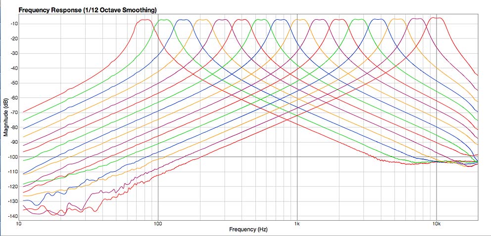
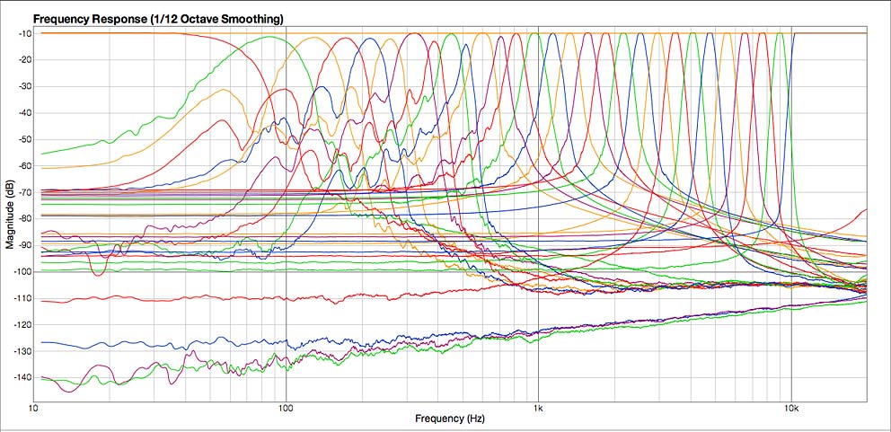
For those interested, Selig did a great job putting together the frequency charts for the 16- and 512 (FFT) -band modes of the Vocoder. Here are the screenshots:

BV512 Vocoder - 16-Band mode Frequency Chart
BV512 Vocoder – 16-Band mode Frequency Chart
BV512 Vocoder - 32-Band mode Frequency Chart
BV512 Vocoder – 512 (FFT) Band mode Frequency Chart

There you have it. Thanks so much to Wendy, Giles, and Allen for these great resources. Your important work does not go unnoticed.

16 – Multiband Anything: Freq. FX

Usually we think of Multiband being reserved for Compression, but why not divide any type of effect, sound, or multiple effects and sounds into different bands using the BV512 Vocoder / Equalizer supplied with Reason. Doing so, you can divide effects and sounds into 32 distinct frequency bands, and that, my friend, can open the doors to a whole wealth of possibilities.

Usually we think of Multiband being reserved for Compression, but why not divide any type of effect, sound, or multiple effects and sounds into different bands using the BV512 Vocoder / Equalizer supplied with Reason. Doing so, you can divide effects and sounds into 32 distinct frequency bands, and that, my friend, can open the doors to a whole wealth of possibilities.

You can download the project files here: multiband-anything This is a zip file which contains an .rns file with 6 Effects Combinators to showcase how you can use the BV512 in Equalizer mode to split different effects to different frequencies in order to process your sound. All the Combinators process the same matrix pattern which is sequencing a Thor synth. Each combinator then outputs the sound to a separate channel on the main 14:2 Mixer. To hear the various effects, mute/solo the specific channels on this mixer.

Starting off Small: Understanding the BV512 Digital Vocoder

The BV512 is a Digital Vocoder which can be used as an EQ device as well. When set in EQ mode, you can select 4, 8, 16, 32, and 512 bands of EQ separation. You’ll have to understand that the 512 bands is an FFT (Fast Fourier Transfer) mode, which for all practical purposes will color your sound and will cause a slight delay in the realm of 20 ms. when processing audio through it. There will only be 32 bands displayed, but each of those 32 bands will actually control a higher amount of bands (512 / 32 = 16 bands each). So for this tutorial and for processing purposes I’m going to stay away from the FFT (512) setting, and instead focus on 32 bands or less (a much more manageable number for the following types of effects).

Just because I’m staying away from using the FFT (512) setting doesn’t mean it’s not useful. Try it out in your own patches, because you never know where you’re going to find that signature sound that makes your brain melt. And in certain situations, I really like the color of the FFT (512) setting.

A Basic Multiband Delay

At it’s simplest, here’s a method to split out a different delay to affect different frequency bands. First, the video. Then the instructions below:

First, Create a Combinator. Then inside, while holding down the Shift key, create a 14:2 Mixer, Spider Audio Merger/Splitter, BV512 Vocoder, and DDL-1 Digital Delay device, in that order.

Set the Vocoder’s Band Count to 16 Bands, and switch from Vocoder mode to “Equalizer” mode.

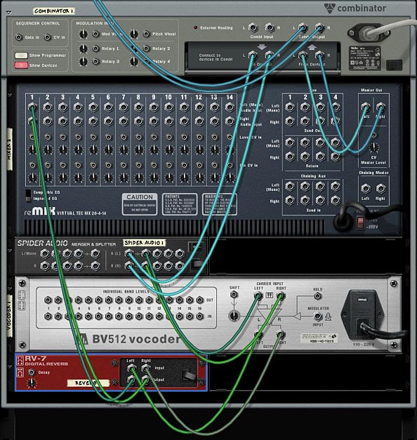
Hit to tab key to flip the rack around  and route the L/R master outs of the Mixer to the L/R “From Devices” of the Combinator. Then route the Combinator’s L/R “To Devices” into the Spider Audio’s main L/R Splitter inputs. Send one pair of L/R split outputs to the Vocoder’s L/R Carrier inputs. Then send the Vocoder’s L/R Carrier outputs to the Delay’s L/R inputs. Finally, send the Delay’s L/R outputs to the Mixer’s L/R channel 1 inputs.

This image shows a single instance of the Vocoder and Delay hooked up to a Channel in the 14:2 Mixer.

Hit the tab key again to flip the rack around to the front. Hold the Shift key (if using Reason), or hold the Ctrl key (if using Record), and select both the Vocoder and the Delay devices. Then right-click and select “Duplicate Devices and Tracks.” Do this two more times to create 4 sets of Vocoder/Delay devices.

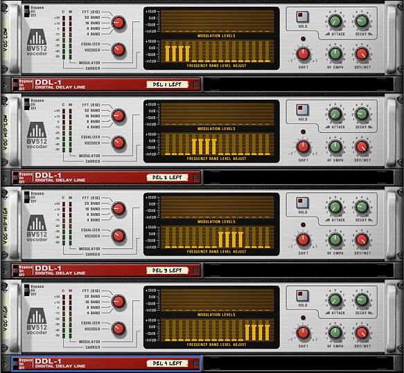
On the first BV512 (the low range), set bands 5-16 to zero. On the second BV512 (The low-mid range), set bands 1-4 and 9-16 to zero. On the third BV512 (the mid-high range), set bands 1-8 and 13-16 to zero. On the fourth and final BV512 (the high range), set bands 1-12 to zero.

The four BV512 devices with their Frequency bands divided, and 4 associated delay units

Set the first Delay unit at the top (the low range) to 1 step, set the second one (low-mid range) to 3 steps, the third one (mid-high range) to 5 steps, and the fourth one (the high range) to 7 steps. This way, each frequency will produce a different delay.

Again, press tab to flip to the back of the rack. Send the other 3 L/R splits from the Audio Splitter into each of the other 3 Vocoder’s L/R carrier Inputs. Then send each of the Delay’s L/R audio outputs to their own Channels on the mixer, so that Channels 1-4 are taken by the Delay Devices outputs.

Now all that’s left is to save the Combinator, and load up your favorite sound to pipe into this effect. To do so, open any instrument and route it’s L/R audio output into the Delay Combinator’s L/R “Combi Input.” Play the sound on your controller keyboard or set up a matrix pattern to sequence the instrument and you’ll hear a different delay for each of the four sets of bands. In other words, the frequency of the sounds you put into the combinator will determine which delay affects the sound. Different frequencies will get different delays applied. Then the sum of all these delayed sounds are mixed into the Mixer, and sent back out the Combinator.

If you give this some thought, you’ll realize that you can apply any number of effects chains to any of the 32-frequency bands of the BV512 to split up effects according to frequency. Furthermore, you can apply this multi-band technique not only to audio and effects, but also to Filters, LFOs and Envelopes which affect the audio. Let’s take a deeper look into how this is done by creating a multiband filter.

MultiBand Filtering: The next step

Now to get a little more complex. Let’s try Filtering our audio based on the Frequency of the incoming signal, and then providing a way to adjust the filter applied to each set of bands. Using our above technique, this becomes child’s play.

Building on the last Delay device we created, select all the DDL-1 Delay units and delete them all.

Then under the first Vocoder, hold Shift down and create a Thor device. Bring all the levels of Thor down to zero (what I call truly initializing Thor). Bring the range on the pitch wheel down to zero, bring polyphony down to zero, bypass all the oscillators and filters, bring all the levels down to zero, and turn all the green buttons off. Leave only the Global envelope Gate Trigger button on, and leave the Global Evelope ADSR envelope in its default position. This way, the envelope can affect Filter 3, which we’ll turn on a little later.

Thor fully initialized, except for the Global Envelope Gate Trig and Tempo Synch Buttons

Now that Thor is much more initialized, go into the MBRS (Modulation Bus Routing Section) and set up the following modulations:

Audio In1: 100 > Filt3 L.In

Audio In2: 100 > Filt3 R.In

Routings in Thor's Modulation Bus Routing Section (MBRS)

Next, duplicate the Thor device 3 times, and place each new Thor under each of the other Vocoders.

Flip the rack around and Move the L/R Carrier output on each Vocoder to the L /R Audio outputs of each corresponding Thor device (1 Mono/Left and 2 Right output on each Thor). Then route new cables from the L/R Carrier output on each Vocoder to the L/R Audio inputs of each corresponding Thor device (Audio In 1 and Audio In 2, respectively on each Thor).

The Back of the Rack showing the Routings for the topmost BV512 device and Thor device

Flip the rack around to the front again, and open up the Combinator’s Programmer. It’s time to add in our Filters and make them adjustable for each set of BV512 bands. For each Thor device, add the following modulations:

Button 1 > Filter 3 Type: 0 / 2

Button 2 > Filter 3 Comb Preset: 0 / 1

Mod Wheel > Filter 3 Res: 0 / 100

Now for each Thor, assign the Filter 3 Frequency to it’s corresponding Rotary as follows:

Thor 1: Rotary 1 > Filter 3 Freq: 1 / 127

Thor 2: Rotary 2 > Filter 3 Freq: 1 / 127

Thor 3: Rotary 3 > Filter 3 Freq: 1 / 127

Thor 4: Rotary 4 > Filter 3 Freq: 1 / 127

The Combinator's Mod Matrix settings for the first Thor

Now when you plug an instrument into this Combinator, you can selectively adjust the filtering of the various frequencies of the sound using the 4 Rotaries of the Combinator. Rotary 1 will affect the low range, Rotary 2 and 3 will affect the mid range, and Rotary 4 will affect the high end.

Where do you go from here

Included in the project files are a set of 6 effects unit that utilize the Equalizer mode of the BV512 to divide the audio source into separate bands and apply effects to each of those bands. Here’s a brief explanation of each:

4 x 16-Band Delay FX: This Combinator uses the Vocoder in 16-band mode to create 4 splits of the audio source going through 4 different delay units. This combinator is the same one created at the beginning of this tutorial, except that there’s an additional delay created under each Vocoder in order to split the delays left and right (for a wider stereo separation). Each rotary controls the delay time for each left/right delay pair. And the buttons underneath each rotary will change the rotary between Steps / MS delay count. A very important feature of this Combinator is the Mod Wheel, which is used as a global Dry/Wet knob for the delay. In its default low-end position, there is no delay. Push the Mod Wheel all the way up and you’ll push the delay fully wet.

8 x 32-Band Delay FX: This combinator is exactly the same as the above 4-way delay, however this uses the Vocoder’s 32-band setting, and splits the signal into 8 different delay units (affecting 4 bands each). Since there’s only 4 rotaries and buttons, you can’t control each delay individually as you can with the previous Combinator. So I opted to put the global dry/wet delay knob on Rotary 1, and put a global steps/ms switcher on Button 1. The only real effect button 1 has is if you want to quickly edit all the delays and have them in MS mode instead, you simply press the button, then go into each delay to edit the delay time.

2-Band Phased Delay FX: This Combinator really was more of an experiment than anything else. The one interesting feature here is that the Vocoder Bands are curved so they blend into each other, rather than have an abrupt frequency change. You can see this on the Vocoder Band area.

Mixed-Band Reverb FX: This combinator uses the Vocoder bands as a notch and Bandpass frequency filter to send your audio through two very different Reverb effects. This goes to show you that there are a lot of possibilities when you start bending different frequencies on the BV512. Use the first Rotary to adjust the Dry/Wet Reverb signal affecting the low and high range of frequencies. Use Rotary 2 to adjust the Dry/Wet Reverb signal affecting the middle range of frequencies. I put a tight small room reverb on the  low & high frequencies and a long hall reverb on the middle range of frequencies to show how drastically you can affect the ambience of your sound by toying with the different frequency ranges.

SuperSpreader FX: This is one way you can get some severe (and almost irritating) amount of stereo separation from a single sound source. I had to add a bunch of ECF-42 envelope filters in order to tame the sound somewhat. You can program this up if it’s to your taste. One thing that I wanted to point out here is that you can use Rotary 1 to invert the Frequencies, thereby flipping them around in real-time or in automation if you want to program the knob in the sequencer. Check out the Modulation Routing inside the Combinator to see how this is done. One drawback is that you can only affect 10 bands at once for any given vocoder, which limits you to using a set amount of band counts. But I’m sure there’s a way to push this limit using CV. Any takers want to give this a shot?

MultiBand Filter FX: Finally, you have the multiband filter FX Combinator which was featured in this tutorial, so I won’t go into too much detail here. Just note that I added a Delay and Chorus on Buttons 3 and 4 if you want to give those a try.

I can almost see the next question on your mind. If we can do all this with the BV512 in Equalizer mode, then what’s to prevent us from applying these same techniques using the MClass Equalizer? The truth is nothing! In fact, you can tailor the MClass Equalizer to a much finer degree than the Vocoder. However, the Vocoder can be a great way to test out quick ideas in a visually intuitive way. And as I hope I’ve shown here, you can still find this device highly flexible and usable. But that being said, there’s nothing stopping you from separating your signals using the MClass EQ, and even combining this with the MClass Stereo Imager to create some very unique Effects Combinators. If you have any ideas or come up with some brilliant effect unit out of this tutorial, please share, comment, and let us know about it.