
In this tutorial I’m going to go over how to create an 8-way Audiomatic Retro Transformer Switcher using the Pads in a Kong device. You can easily add all 16 on all Kong Pads and then switch between any of them using your Pad Controller or Key Controller. Or you can use a built-in randomizer. This is just one idea I came up with out of a discussion with Kurt Kurasaki on Facebook. So I thought I would share it with everyone.
With the advent of Reason 7, you get the Audiomatic Retro Transformer Rack Extension for free. This is like Instagram for photos, except it creates musical snapshots that can be applied to the whole mix or individual tracks. So I thought, why not create an FX combinator where you can select different Audiomatic presets using the Kong pads. The added benefit is that you can switch between them in real-time at any point you like using automation. I even added a bypass so that when an audiomatic preset is not selected, the original audio is passed through unaffected. Or, there’s a method to play it parallel with the original loop.
You can download the project files here: 8-way-audiomatic-kong-switcher. There’s 2 Combinator files included. One file with an audio bypass, and one without. It requires Reason 7.0, Audiomatic Retro Transformer and Directre.
The Audiomatic Retro Transformer Instantaneous Switcher
- Create a Dr. Octo Rex Loop Player. Click the Browse Patch folder icon and open the AC Guitar | Open Strums Key of A 90 bpm.drex patch. This provides a sound source for our Combinator FX setup.
- Hold down Shift and create a Combinator. Click the Show Programmer button.
- Inside the Combinator, create a Mixer 14:2. Reduce the Level Faders on Channels 1-8 all the way to 0. We’re going to control the volume of these Channels using Kong.
- Hold down Shift and create a Kong Drum Designer. Relabel pads 1-8 in the following way:
Pad 1 = Spread
Pad 2 = Radio
Pad 3 = VHS
Pad 4 = Vinyl
Pad 5 = Tape
Pad 6 = Hi-Fi
Pad 7 = Bright
Pad 8 = Bottom
- Hold down Shift and create a Directre Audio Router. Turn on all 8 Channels using the Enable buttons. We’ll use this to split the incoming audio out to 8 different Channels on Directre (note that you can also use another Mixer 14:2 for this task, instead of Directre).
- Hold down Shift and create 8 Audiomatic Retro Transformer devices. Label them the same way you labeled the first 8 Pads on Kong above. Then switch each device’s Preset to the corresponding label. In this case, we will have 8 Audiomatic devices, each with a different preset. The basic premise is to send audio splits from each Directre output into the Audiomatic, and then send that back out to the Main Mixer and then out of the Combinator.
- Hold down Shift and create a Thor device. Click the Show Programmer buttton. Name the Thor device “Sequencer.” On the Global panel, set the Pitch Bend range, Polyphony, and Release Polyphony to 0. Relabel Button 1 “Trig Step Seq” and disable both the MIDI & Step Seq buttons. In the Programmer panel, turn off Oscillator 1, disable routing Oscillator 1 from the Mixer to Filter 1 by deselecting the “1” button, bypass Filter 1, and turn off the Global Envelope. Rename Thor 1 “Bass Filter” and Thor 2 “Snare Filter” (see image at right). Enter the following into the first line of the Modulation Bus Routing System (MBRS):
Button 1 : 100 > S. Trig [This allows you to enable the Run button on Thor’s Step Sequencer from Thor’s Button 1]
- Still inside the “Sequencer” Thor, set the Run Mode to Repeat, and the Direction to Random. Set the Octave Switch to 4. Create an 8-step sequence where each step is set to subsequent Note values from C1 to G1. Since these notes trigger Kong’s first 8 pads via the internal MIDI Pad assignments, we’re setting up Thor to trigger these Pads randomly.
- Still inside the “Sequencer” Thor device, switch the Edit rotary to “Gate Length” and set all 8 steps to 100%. This ensures that switching among Audiomatic presets is instantaneous, as it takes up the full length of the gate. Going from one to the other is a smooth transition.
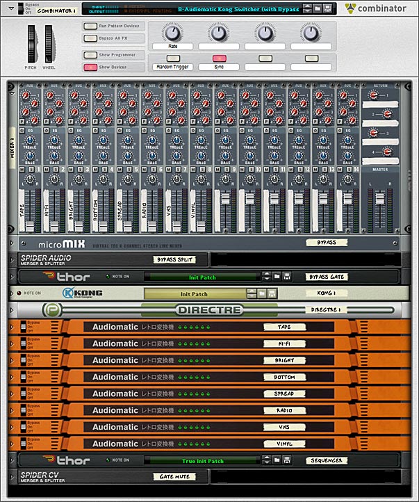
The front panel showing all the devices in the Audiomatic Retro Transformer Combinator patch. - Tab to the back of the rack. Move the left / right Main Output cables from the Dr. Octo Rex to the left / right “Combi Output.” Create a new audio cable pair from the left / right Main output of Dr. Octo Rex to the left / right “Combi Input.” Create another audio cable pair from the Combinator’s left / right “To Devices” to the left / right “Main In” on Directre.
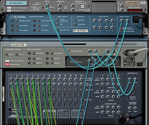
The back of the rack showing the routings between the Dr. Octo Rex and the Combinator, as well as the routings for the Main Mixer. - Send Channels 1-8 left / right Direct Out from Directre into the 8 Audiomatic left / right inputs. Then send the left / right outputs of all 8 Audiomatic devices into the first 8 Channels on the Mixer 14:2.
- On Kong, send the first 8 Pad Gate Out CV cables to their respective Level CV In on the Mixer 14:2. However, set it up so that Pads 1-4 on Kong are going into Channels 5-8 on the Mixer, and Pads 5-8 on Kong are going into Channels 1-4 on the Mixer.
- Finally, on the “Sequencer” Thor device, send the Note & Gate/Velocity from Thor’s Step Sequencer into the Kong’s CV & Gate inputs. This sets up Kong to be sequenced from Thor.
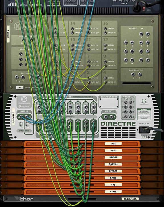
The back of the rack showing the routings between the Mixer, Kong, Directre and the Audiomatic devices. - Tab to the front of the rack. On the Combinator, label Rotary 1 “Rate,” Button 1 “Rnd Sequence,” and Button 2 “Sync.” In the Programmer, select the “Sequencer” Thor device in the Key Mapping area, and enter the following in the Modulation Routing section:
Rotary 1 > Synced Rate : 0 / 20 [Ensures you have access to the full rate of Thor’s sequencer via Rotary 1 on the Combinator]
Rotary 1 > Free Rate : 1 / 2,500 [Ensures you have access to the full rate of Thor’s sequencer via Rotary 1 on the Combinator]
Button 1 > Button 1 : 0 / 1 [Since Thor’s Button 1 sets the Sequencer in motion, this Button turns the Sequencer on when enabled]
Button 2 > Synced : 0 / 1 [Syncs Thor’s Step Sequencer to the Rate to the Song Tempo when enabled]
- Set Rotary 1 on the Combinator to 72 (which equals a rate of 1/4 in the Sequencer). Then press Button 2 to set the Sequencer to Sync mode (even though it’s already set up like this by default, it engages the button to operate in Sync).
Press the Run button on the Dr. Octo Rex or press play on the Transport. This starts the Dr. Octo Rex guitar loop. You won’t hear anything though, because there’s no audio bypass. However, when you now press Button 1 on the Combinator, Thor’s Sequencer is set in motion. This, in turn, triggers the Kong Pads to play the first 8 pads randomly (and this, I should add, is wonderful for many different applications). However, you may want to play the Pads manually, or from your Pad Controller, without using the Thor sequencer. You can do this by creating a track for Kong and then going nuts on the first 8 pads. Since the audio is always going through all 8 Audiomatic devices, the switch from Pad to Pad is instantaneous. However, when no pad is pressed, you won’t hear anything. So let’s set up our Combinator so that if the Pads are not pressed, the original audio still passes through. The following explains how to set this up.
Setting up an Audio Bypass
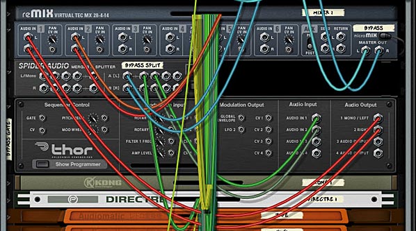
- Continuing with our above tutorial, go inside the Combinator and select the Mixer 14:2. Hold Shift down, and create a Line Mixer 6:2, a Spider Audio Merger / Splitter, and a Thor. Name the Line Mixer “Bypass,” the Spider “Bypass Split,” and the Thor “Bypass Gate.”
- In the “Bypass Gate” Thor device, set the Pitch Bend Range to 0, the Polyphony & Release Polyphony to 0, and click the Show Programmer buttton. Turn off Oscillator 1, disable routing Oscillator 1 from the Mixer to Filter 1 by deselecting the “1” button, bypass Filter 1, and turn off all the Envelope (Gate Trig) buttons. Enter the following in the first 2 lines of the MBRS:
Audio In1 : 100 > Audio Out1 : -100 > MIDI Gate
Audio In2 : 100 > Audio Out2 : -100 > MIDI Gate
- The negative MIDI gate values in the MBRS mean that the original unprocessed sound will shine through when the keys are NOT played. They will also cut the sound when the keys ARE played. In this case, since you have the effects loaded on the keys, the FX signal will take over and you’ll hear the effects processing the sounds while those keys are played. Click the Show Programmer button again to fold up the “Bypass Gate” Thor device.
- Tab to the back of the rack, and Move the Directre’s left / right “Main In” audio cables to the “Bypass Split” Spider’s left / right Split Inputs. Send Split 1 left / right outputs on the “Bypass Split” Spider back into the Directre’s left / right “Main In.” Then send a second Split from the “Bypass Split” (Split 2) left / right outputs into the “Bypass Gate” Thor device’s Audio In 1 / Audio In 2.
- On the “Bypass Gate” Thor device, send 1 / Left & 2 / Right Audio Outputs into the Channel 1 left / right inputs on the “Bypass” Line Mixer. Move the left / right Master Outputs from the Mixer 14:2 into the Master Outputs of the “Bypass” Line Mixer. Then create a new audio connection from the left / right Master Outputs of the Main Mixer 14:2 to the Channel 2 left / right inputs on the “Bypass” Line Mixer.
Tab to the front of the rack. So far we’ve set up the routing for the bypass. As it stands now, if you press Run on the Dr. Octo Rex, you’ll hear the original loop. If you then press Button 1 on the Combinator, you’ll hear BOTH the original Loop and the Audiomatic Preset playing at once (in a Parallel manner). To set things up so that you don’t hear both at once do the following:
- Hold Shift and create a Spider CV Merger / Splitter at the bottom of the Combinator’s device stack. Tab to the back of the rack. Move the “Sequencer” Thor’s Gate / Velocity CV output from the Step Sequencer into the A Split 1 on the Spider CV Splitter. Then create a new CV cable from the “Sequencer” Thor Gate / Velocity CV output into the Spider CV Splitter’s A input. Send another Split (A Split 2) into the Combinator’s CV 1 Input. Change the CV Switch on Input 1 to Unipolar.
- Tab to the front of the rack, and in the Combinator, select the “Bypass” Line Mixer in the Key Mapping area. Enter the following in the Modulation Routing section:
CV In 1 > Channel 1 Mute : 0 / 1
When you press Run on the Dr. Octo Rex, you’ll hear the original loop. If you now press Button 1 on the Combinator, the original loop is muted, and only the Audiomatic preset affecting the loop will be heard. Note that with this setup, you cannot play the pads individually via your Pad Controller. If you do, you will still hear the parallel processed configuration with both the Original and processed loop at the same time. However, this gives you two methods to control the Audiomatic switching effect.
That’s it for now. Hope you find this idea useful. Try your hand at creating a 16-way switcher if you like.


