25 – No-Nonsense Tips (Part 2)

In this second part, I’m going to provide even more quick tips that can be used as food for thought while you develop your tracks. These aren’t earth-shattering or advanced. They are just some easy tips to help out with some problems you might have or tips that show you a few capabilities you may have missed.

In this second part, I’m going to provide even more quick tips that can be used as food for thought while you develop your tracks. These aren’t earth-shattering or advanced. They are just some easy tips to help out with some problems you might have or tips that show you a few capabilities you may have missed. So let’s jump in.

Tip #1: Did you know this could be Automated? I didn’t.

This is probably the simplest of tips. While I learned about a year ago that you can assign the Destination and Scale Amount parameters from Thor’s Modulation Bus Routing System (MBRS) to a rotary on a Combinator, I completely neglected to realize that you can indeed automate any of the “Amount” parameters directly in Thor. So for example, if you setup a Vibrato in Thor, it would look something like this:

LFO2: 25 > Osc1 Pitch: 100 > ModWheel (Read Thor’s back panel — this is your basic Vibrato).

Great, but now, let’s automate that LFO2 amount so that the vibrato increases or decreases the pitch over time. Easy as easy can be. Simply right-click over the amount parameter on the front of Thor in the MBRS and select “Edit Automation.” Now you can automate the amount directly in the Sequencer. Pretty cool right?

The Amount settings in Thor's MBRS can also be automated

Tip #2: Stealing unused CV from devices that are already there.

This is a great tip, and it’s one I use all the time. Let’s say you have most of the sound sources set up in your track. Now you want to modulate and automate parameters. Instead of creating new devices like the Subtractor, Malstrom, Matrix, etc. to modulate those destinations, why not steal modulation sources from the devices that are already in your track. This saves on CPU, and it means you ultimately have a less cluttered rack with less devices. The only thing you need to be careful about is making things overly complex, as it can get confusing quickly. But this is another trick I use all the time.

For example, if you have a Thor as one of your devices in your rack, you have access to a multitude of CV sources you can use to modulate other parameters and devices. Here’s just a few:

  • Curve 1 in the Step Sequencer
  • Curve 2 in the Step Sequencer
  • LFO 1
  • LFO 2
  • Mod Envelope
  • Amp Envelope

So if any of these are not currently being tapped for use by the Thor sound itself (and even if they are, you can still use them for other purposes), you can enlist them for CV duty anywhere else in your rack. Simply create the CV connection from the back of Thor to the destination CV input in the other device location. If you are using LFO2 or the Global Envelope outputs, then all you need to do is set up the LFO 2 or Global Envelope parameters on the front of Thor and you’re done. If you are using LFO 1 or the Amp envelope, you’ll have to set these up using the CV outputs on the back of Thor, and then setting them up in the MBRS. If using the Curves in the Step Sequencer, you can route the CV from the Curve CV outputs on the back of Thor.

You literally have an amazing supply of CV modulation sources all from one Thor device. So much so, that this may be all you need. You might not need to use the LFO from another Subtractor or the Mod A and B from a Malstrom, and you may not need to add a bunch of Matrix units. With Thor, you can keep everything contained in one location. And chances are that you probably already have a Thor unit in your track already. So save yourself some CPU. That reminds me to put together a tutorial on all the CV possibilities of Thor. hmmm. Perhaps in a tutorial down the road. More to come on this. . .

Tip #3: Add a Scream to shape your sound.

I have to say that this came out of watching Hydlide run through some videos about my latest refill. He had a really solid idea to turn pretty much any drum sound into a punchier kick sound. But this is also a nice trick to try out variations on your own sound and is kind of like the tip I showed you where we added a unison to give things a wider thicker sound. This time however, let’s add a Scream device after any sound source and just play with the settings until it shapes into a sound you like. Something a little beefier or meatier. And it only takes a minute or so.

The other added benefit to doing this is that you have access to a 3-band EQ using the “Cut” section. While this isn’t as powerful as the M-Class EQ, it does a great job for quickly sculpting the sound. So when you’re in a rut, try out a Unison on those thinner synth sounds, but try out a Scream as well, to sclupt your drum and bass sounds.
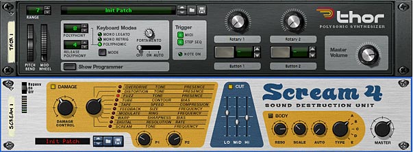
The Scream can be inserted anywhere as a great sound sculpting tool

Tip #4: Turn your Combinator buttons into Radio buttons.

This tip came out of a request on the PUF (Propellerhead User Forum) where the original poster wanted to convert the Combinator buttons into Radio buttons. If you don’t know what a Radio button is, it’s ok. You’ve used them everyday in all kinds of software. Here’s a quick rundown: Radio Buttons.

You can download the template for this trick here: radio-buttons. The zip file contains the RNS file (and Combinator) which turns your Combinator buttons into radio buttons. Don’t pay too much attention to the synths at work here. They are just put there at random to highlight the difference in sound when selecting each of the buttons. I didn’t choose them for their stunning sound quality when played together (reset).

Now as all of you know, you can’t change the way the buttons work. They are toggle buttons by design, turning something on or off. So to turn them into a radio button is like taking a two-dimensional object and turning it into a one-dimensional object. It’s going backwards slightly. But there’s a good reason behind it.

To start, you probably want to have the buttons trigger something. In this case, I’ll take something very basic like 4 synths tied to each of the 4 buttons. Pressing one button will trigger its corresponding synth. Pressing another button will trigger the next synth, and so on. So first create a Combinator, and inside create four 6:2 line mixers and four synth devices. And then tie each of the synths to its own line mixer by sending the audio output to channel 1 on each of the four line mixers. Then open up the Combinator programmer, and program the following:

Line Mixer 1:

Rotary 1: Master Level: 100 / 100

Button 1: Master Level: 100 / 100

Button 2: Master Level: 0 / 0

Button 3: Master Level: 0 / 0

Button 4: Master Level: 0 / 0

Line Mixer 2:

Rotary 1: Master Level: 100 / 100

Button 1: Master Level: 0 / 0

Button 2: Master Level: 100 / 100

Button 3: Master Level: 0 / 0

Button 4: Master Level: 0 / 0

Line Mixer 3:

Rotary 1: Master Level: 100 / 100

Button 1: Master Level: 0 / 0

Button 2: Master Level: 0 / 0

Button 3: Master Level: 100 / 100

Button 4: Master Level: 0 / 0

Line Mixer 4:

Rotary 1: Master Level: 100 / 100

Button 1: Master Level: 0 / 0

Button 2: Master Level: 0 / 0

Button 3: Master Level: 0 / 0

Button 4: Master Level: 100 / 100

You’re pretty much done. Now, the buttons act as rotaries. However, you’ll have to disregard the fact that they light up at all. The fact that they are enabled or disabled means nothing. The only thing that means anything is if you switch from one button to the next. Remember our analogy: we’re taking a 2-dimensional object and turning it into a one-dimensional object. There’s no toggling. It’s a straightforward button to button switch.
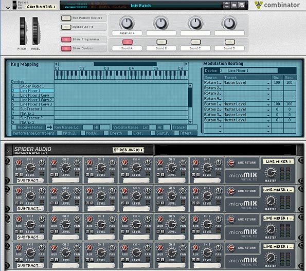
The front of the Combinator showing the Programmer and the Line Mixers. The Synths are stacked underneath.

Also, Rotary 1 acts as a “Reset” button. Turning this rotary to any location will turn all four attached synths on at the same time. The reason I did this is due to the fact that when you start pressing buttons you will only be able to hear one synth at any given time and there was no way to “go back” to having all of the synths on at once. So I programmed the rotary to do this. As any good programmer knows, you should always provide a way to get back to the default. So this was my “Default” — however, if you don’t need it, you can remove the programming behind Rotary 1 if you really want to.


As always, I hope you enjoyed some of these quick tips. They are definitely fun to figure out and dream up. So keep the questions coming, and share some of your favorite tips with the rest of us. Happy Reasoning!

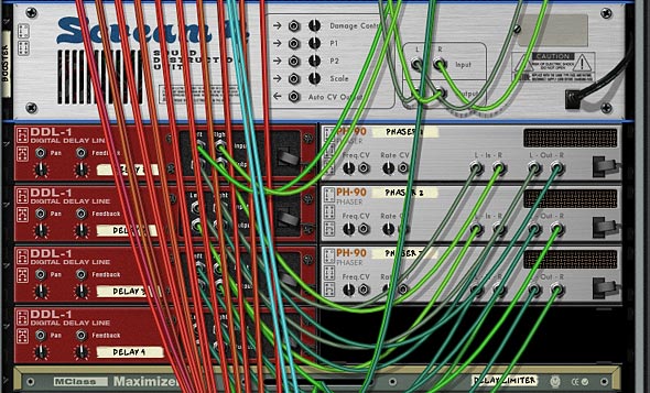
Auto Glitcher Effect

This is a Combinator which can be used to apply some Glitchy fun to any audio source you throw at it. It uses a Scream Distortion unit, 3 delays, and 2 Phasers which are controlled by some Malstrom Curves.

Download the Combinator: Auto-Glitcher

Description: This is a Combinator which can be used to apply some Glitchy fun to any audio source you throw at it. It uses a Scream Distortion unit, 3 delays, and 2 Phasers which are controlled by some Malstrom Curves.


 Here’s the complete rundown of the Combinator controls:

Pitch Bend: Unassigned

Mod Wheel: Affects the Rate of the Modulation curve which is tied to the Scream Damage Type. Raising the Mod Wheel makes Damage Type switching faster. Lowering the Mod Wheel makes Damage Type switching slower.

Rotary 1: Don’t Touch!: This Rotary is tied to the Damage Type of the Scream, but is controlled by the Malstrom Mod A Curve, and so does not need to be moved.

Rotary 2: Don’t Touch!: Like the previous Rotary, this one is tied to the Body Type of the scream, and is controlled by the Mod B Curve of the Malstrom, so it does not need to be moved.

Rotary 3: Damage: This controls the amount of Scream Distortion Damage applied to the sound source. Turned fully right, and you’re applying about 50% of damage to the signal (64). Turned fully left, and you’re applying very little damage (10).

Rotary 4: Wave: This controls the Malstrom Wave type (Modulation A Curve) which affects the Damage Type selection on the Scream. You can scroll through all 32 different wave forms in real time.

Button 1: Synch Off / On: This turns on the Synch on the Malstrom’s Mod A Curve (which controls the Scream Damage Type switching). When pushed in, Synch is on. When the button is off, the Synch is off.

Button 2: Body Off / On: This turns on the Body section of the Scream. When pushed in, the Body section is on, when the button is off, the Body section is turned off.

Button 3: Multi / Single Delay: This turns on the Multi-tap delay. When the Button is left off, the last delay in the sequence is the only one on (providing a simple delay to your sound source. When turned on, you have a full-on Multi-tap delay assault, with two Phasers in the mix as well.

Button 4: Damage Off / On: This turns the Damage on or off. When the button is left off, the Scream is bypassed, and when the button is on, the Scream unit is left on. It’s worthwhile to note that if you turn off the Damage, The Mod Wheel, and all the Rotaries will do nothing to your sound. The nice thing about Button 2, 3, and 4 is that you can minimize or maximize the amount of Glitch that is applied to the sound. For example, if you want to hear only a single or multiple delay, just turn leave button 4 off. If you want only the damage with no multi-tap, just turn off button 3. And finally, if you want the damage without the body section, just turn off Button 2. In this way, you can control what effects you want applied to your sound.

Other Notes: Feel free to change any of the Malstrom Mod Curves to curves that you like. Of course, for the Mod A curve on the Malstrom controlling the damage type of the scream, you don’t need to change this curve manually. You can change this using Rotary 4 (Wave). Or, if you want, you can also map any of the Curves to the “Wave” Rotary and have them move in unison together (or flip the min/max settings to change things up a bit). Alternately, you can program Rotary 1 to affect both the Damage and Body Types on the Scream, which could free up a Rotary for you. However, it would also mean that the Body type and Damage type would be using the same curve to control both those parameters.

Let me know if you find this patch useful and if you have any other suggestions for ways it can be made better? Or if you have some suggestions for other ways to get some glitchy fun out of Reason.

13 – Glitch Boxes

In this project, I’m going to create a few Glitch Boxes, and show you some techniques to get a little more glitch out of Reason. Though Reason isn’t built to be a glitch plugin, there are several ways you can connect things up to get some glitch mayhem from the devices.

In this project, I’m going to create a few Glitch Boxes, and show you some techniques to get a little more glitch out of Reason. Though Reason isn’t built to be a glitch plugin, there are several ways you can connect things up to get some glitch mayhem from the devices. When you then combine them all, you can have yourself a field day playing around with the knobs, wheels and buttons and work them into your own compositions.

So here I’m going to provide 3 different Glitch Boxes (incidentally they are color-coded just for fun), and go over some of the techniques that I think make them unique. Before I start, let me point out that I’m not going to go through the process of creating the Combinators from start to finish. Rather, I’m going to use the technique I outlined in the “Creative Redrum” tutorial series, where I added 10 synths and used gate triggering from the redrum to play these synths. The synths are the main glitch sounds, and these can be anything you like. The point is how you can use those sounds inside the combinator, and how you can add stylistic effects to get more out of them.

So let’s start our glitch journey in Reason.

The file for this tutorial can be found here: Glitch Boxes. The zip file contains 3 Combinators inside an .RNS file, each of which is attached to a mixer. To hear one of the combinators, just mute the other ones on the mixer. They weren’t designed to be played together, however, this was the easiest way to provide them to you all at once. Feel free to save them as Combinator patches and/or use them as templates where you can add in your own sounds into each of the 10 different synths in each of the Combinators. Also, don’t forget that you’re not only getting access to 3 patches, but you’re getting access to 30 synth glitch sounds as well. Enjoy!

Glitch Box 1 (Blue – Thors)

This Glitch Box uses 10 Thors to generate 10 different Glitch sounds, which are triggered by the Redrum Sequencer. The Redrum in turn has 32 patterns which are 64 steps each for a maximum Glitch mayhem. The interesting part of this patch is the way the Auto-sequencer is setup. By pressing the fourth button on the Combinator, the Auto-Sequencer kicks in and takes control to provide a very random output. It’s very easy to set this up. You just need to create a few Matrixes, and then send the Curve (or Note or Gate) CV into the Combinator CV inputs to control the overall playback of the Combi, or else any one of the Rotaries or Pitch/Mod wheels.


The rest of the Combinator patch is similar to the Creative Redrums 2 and Creative Redrums 3 tutorials, so I’m not going to delve into that right now. Please feel free to read through those tutorial in order to get familiar with the methods used to put together these patches. 

Here is a rundown of how this Combinator’s Rotaries and Buttons work:

Pitch Wheel: This raises or lowers the pitch of the 10 Glitch sounds at once by +/- 7 semitones.

Mod Wheel:  This dampens the sound of the Higher pitched Glitch sounds, essentially making things a little less sibilant.

Rotary 1:  Vocoder Filter – This Rotary affects the Thor Vocoder Modulation Filter. Use this knob to change the affect the filter has on the Vocoder. Basically, use this knob to dial in a sound filtering that appeals to you.

Rotary 2: Shift – This Rotary is used to raise or lower the “Shift” parameter of the Vocoder. Again, you’ll have to experiment with this knob to see what sounds best for you. You can also use it to create some interesting sweeps.

Rotary 3:  Pattern Sequencer – This knob allows you to select from 32 different Glitch patterns (all with 64 steps each). If you want to turn the patterns off, you can by turing the Rotary completely left (at zero). This turns off the patterns entirely so no sound signal will get generated.

Rotary 4:  Master Level – This is the Main Mixer’s master level. It allows you to fine-tune the volume of the overall mix.

Button 1:  Doubler – This essentially doubles the Glitch sounds. Beware, it can add a ton of beats. But if you mute a few of the glitch sounds on the Mixer or Redrum devices, you can have some fun using this button to thicken up and beef up your beats by automatically doubling them.

Button 2:  Alternate Filter – This adds a different filtered sound to the Glitch Box. It can be used to extend the Box to a whole new range of sounds. Experiment to see what you can do with this filter.

Button 3:  Master Bypass – This Button will bypass the Vocoder FX as well as the Mastering devices. If you want a very raw sound, this is the button to press.

Button 4:  Auto-Sequence – This button applies a random auto-sequenced element to the Glitch box. It not only acts as the note/gate CV for the Combinator, but also randomizes the first two Rotaries (the Vocoder Filter and Vocoder Shift parameters).

Glitch Box 2 (Red – Malstroms)

This Glitch Box uses 10 Malstroms to generate 10 different Glitch sounds, which are triggered by the Redrum Sequencer. The Redrum in turn has 32 patterns which are 64 steps each for a maximum Glitch mayhem. The interesting part of this patch is the way in which there are multiple Delay and Phaser units attached to the audio signal at the end. This creates a multi-tap delay effect which can be applied selectively.

Multi-Tap Delay setup (with Phasers)

Here is a rundown of how the Combinator Rotaries and Buttons work:

Pitch Wheel: This raises or lowers the pitch of the 10 Glitch sounds at once by +/- 7 semitones.

Mod Wheel:  This completely changes the type of sounds produced by the Glitch devices. Each Malstrom device was programmed to generate something totally wacky and off-the-wall when the Mod Wheel was used. So here is the result. Have at it!

Rotary 1:  Vocoder Filter – This Rotary affects the Thor Vocoder Modulation Filter. Use this knob to change the affect the filter has on the Vocoder. Basically, use this knob to dial in a sound filtering that appeals to you.

Rotary 2: Shift – This Rotary is used to raise or lower the “Shift” parameter of the Vocoder. Again, you’ll have to experiment with this knob to see what sounds best for you. You can also use it to create some interesting sweeps.

Rotary 3:  Pattern Sequencer – This knob allows you to select from 32 different Glitch patterns (all with 64 steps each). If you want to turn the patterns off, you can by turing the Rotary completely left (at zero). This turns off the patterns entirely so no sound signal will get generated.

Rotary 4:  Multi-Tap Delay – This adds some multi-tap delay effect to the glitch sounds. The Rotary acts as a dry/wet knob, so turning it fully left turns the delay off (dry), and turning it fully right turns it fully on (wet). Be careful as it’s easy to overdo it, and sometimes if other parameters are turned on (like Booster), the delay can get pretty loud. Though I’ve tried to limit the loudness of the delays with a Maximizer device. Just be careful not to overuse. 😉

Button 1:  Filter Type A/B – This changes the Thor Vocoder Modulation Filter from a simple Noise Oscillator to a different type of Noise Oscillator, and then adds in a Mixed sine Wavetable Oscillator into the mix. Try it out to change the sound entirely.

Button 2:  Bands 4/32 – This switches the Vocoder Band count from 4 (not pressed) to 32 (pressed in). Use this to keep the sound thin with 4 bands, or thicken it up with 32 bands.

Button 3:  Hold – This triggers the Hold button on the Vocoder. This can add some interesting unpredictible outcomes if pressed every so often. Or create a stutter effect by programming it to hold every bar, beat, or at random throughout your track.

Button 4:  Booster – This adds some emphasis and warmth to the sound via a Scream device.

Glitch Box 3 (Green – Subtractors)

This Glitch Box uses 10 Subtractors to generate 10 different Glitch sounds, which are triggered by the Redrum Sequencer, just like the other Glitch Boxes above. There’s 32 patterns which are 64 steps long, again like the other Boxes. There are a few interesting things happening in this patch, which I’ll go through one at a time.

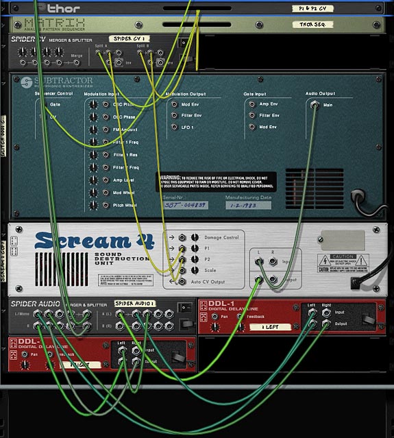
First, there are Scream Distortion units attached to each of the 10 sounds. The Screams are randomly sequenced to switch using the Matrix “FX Sequencer.” The Curve CV is cabled from this matrix to Rotary 4, which in turn is set to program all the Scream units to various degrees.

Second, there are two Digital Delay units attached to each of the glitch sounds. One unit is set up for the left, and the other for the right. Then they are merged together and sent back to the mixer. By changing the steps associated with each of these devices, you can set up some very complex delay patterns, which in turn enhances the “Glitch” element for each of the sounds.

The anatomy of a single Subtractor Glitch sound with Scream and Left/Right Delay FX

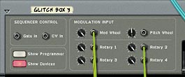
Third, Auto-Sequencing is set up so that there is an even more random element added to the box. Here, a matrix is set up for each Rotary as well as the Mod Wheel.

Auto-Sequencing the Mod Wheel and first 3 Rotaries. The fourth is controlled by the Matrix FX Sequencer.
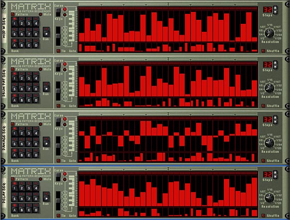
The 4 Matrixes controlling the Mod Wheel, Pattern, Delay, and Scream Damage

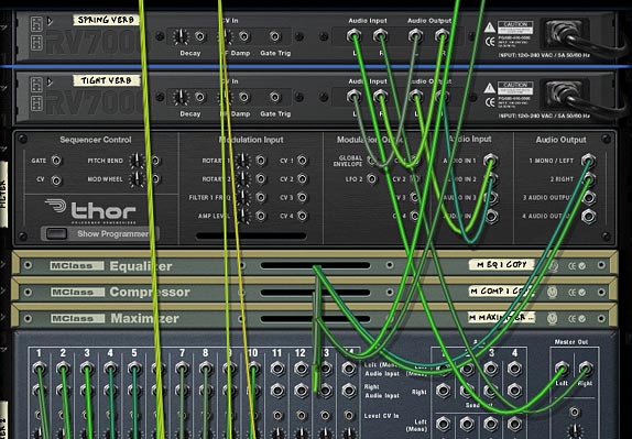
Fourth, there are a few other effects added into the Mix. If you’ve read some of the other articles, you’ll no doubt be familiar with ways in which the audio can be routed through Thor, and thereby use Thor’s filters on the audio signal chain. So I’ve added an alternate filter using this method. In addition, there are two Reverbs set up at the end of the signal chain in order to add a bit of room where the glitch sounds can feel at home.

Routing the Audio through a Thor Filter, as well as the 2 Reverbs

Fifth, and finally, The P1 and P2 parameters on the Scream devices are controlled via CV by a Thor device. The setup is that LFO1 controls P1, and LFO2 controls P2. So if you want to control these two parameters on every Scream device simultaneously, all you have to do is make changes to the LFO1 and 2 parameters in the Thor “P1 & P2 CV” device. This can help add some further Glitchy fun with the sound (especially when the Damage Type keeps changing randomly).

Here is a rundown of how the Combinator Rotaries and Buttons work:

Pitch Wheel: This raises or lowers the pitch of the 10 Glitch sounds at once by +/- 4 semitones.

Mod Wheel:  This affects a few of the Glitch sounds, but not too much. It’s pretty much unassigned.

Rotary 1:  Drum Pattern – This knob allows you to select from 32 different Glitch patterns (all with 64 steps each). If you want to turn the patterns off, you can by turing the Rotary completely left (at zero). This turns off the patterns entirely so no sound signal will get generated.

Rotary 2:  Delay Dry/Wet – This Rotary allows you to apply Delay to the Glitch sounds in a very random way (depending on how the steps are set up in each of your DDL devices. I can only recommend that you play around with the settings in these units, especially varying the steps on each unit). The Rotary acts as a dry/wet knob, so turning it fully left turns the delay off (dry), and turning it fully right turns it fully on (wet).

Rotary 3:  Damage Dry/Wet – This works the same way as the delay does (Dry/Wet), but this time the Scream’s damage knob is affected for all the Scream units. Be careful not to go too far overboard as you can end up making the sound pretty loud. I tried to limit it already a little bit by cutting off the amount of damage that can be applied, but it can still cause pretty loud signals. So just use it cautiously and always be on the lookout for your levels and clipping.

Rotary 4:  Glitch Hi <-> Lo – This essentially will turn off the amount of randomness applied to the Scream devices “Damage Type.” The way the Screams are set up, the matrix controls the damage type and randomly shifts from one type to another using CV to control this knob. If you keep it fully left, the Screams are at their most random; receiving switching cues from the matrix. When the knob is turned fully right, the damage type will not change at all and will stay fixed. So this Rotary controls how much randomness is applied to the Scream Damage Type, or rather how much switching between Damage Types will take place.

Button 1:  Spring Verb – This applies a spring reverb to the entire mix. Feel free to change the RV 7000 patch to anything that you feel suits this sound.

Button 2:  Tight Verb – This applies a tight reverb to the entire mix. Feel free to change the RV 7000 patch to anything that you feel suits this sound.

Button 3:  Comb Filter – This adds a comb filter to the entire mix to quickly change the Glitch sound. Feel free to change this in the Thor “Filter” device, if you like. It’s in the “Filter 3” slot.

Button 4:  Auto Sequence – This button applies a random auto-sequenced element to the Glitch box. It randomizes the Mod Wheel, and first 3 Rotaries (Drum Pattern, Delay, and Damage).

I hope this article provides a few new ways you can add to your Glitch fun in Reason. There’s probably a million different ways you can add Glitch into your tracks. I know Ed from EditEd4TV fame has just come up with a beat repeater that is quite amazing and interesting to look at. Visit the PUF (Propellerhead User Forum) for more information. And if you have any other ideas for ways in which you can make Glitch come to life in reason, please let me know. I’m always interested to hear about your techniques. Don’t be shy. Share them! And until my next installment, have fun in Reason and Record.

Cheers.

8 – Auto CV (Chasing Audio)

Learn how to use the Scream’s Auto CV output to convert an audio signal into a CV signal. Also learn how Thor can be used to achieve a similar effect, and how you can use Thor to switch between different CV sources.

We don’t live in a vacuum (well maybe sometimes we do, however, for the most part we learn by experimenting with many different elements from different sources) and so this tutorial will build upon a previous tutorial on using Thor’s CV capabilities to switch between 2 different CV sources. In addition, there will be a new element which shows how the Auto CV on the back of the Scream can be used to follow the audio from a Dr. Rex. And this is really the heart of the tutorial.

The “Auto CV” feature on the back of the Scream device is an envelope follower with a twist. While most envelope followers work on Audio and in essence shape the parameters of the audio, the Scream’s envelope follower follows the audio, and then converts that to a CV signal. Before Reason 4, this was the only way you could essentially create a CV signal from an audio source. With the advent of Reason 4, you can use Thor to perform the same functions. Even so, it’s worthwhile to note how the Auto CV works in the scream, as it can still be used effectively, with the added bonus that it leaves a lighter CPU footprint, and allows you access to the Scream as an FX insert as well. Finally, I’ll touch upon how you can achieve a similar effect using Thor.

The project files can be downloaded here:  auto-cv-chasing-audio It contains three Combinators which are used as examples to show the Auto CV setups described below. A matrix is used to play a random pattern so you can hear the results. All Combinators play simultaneously through the main mixer, so don’t forget to mute or unmute the channels to hear the proper example.

Using the Scream Auto CV to convert Audio into CV

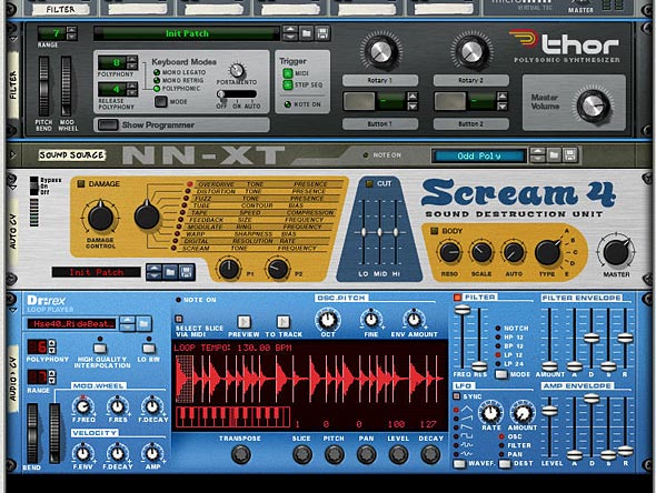
  1. Create a Combinator and a 6:2 Line Mixer. Then holding shift down, create in order a Thor, NN-XT, Scream and Dr.Rex device.
  2. Click the Show Programmer button in Thor, and turn off Oscillator 1, Bypass Filter 1, and click the “1” button next to the Filter 1 slot. Add a Low Pass Ladder Filter in the Filter 3 slot. Finally, click the Delay button to turn on the Global Delay.
  3. In the NN-XT open up the patch browser and navigate to the Factory Soundbank. Go to the NN-XT Sampler Patches > Synth Poly and open the Odd Poly patch.
  4. In the Scream device, turn off the “Damage” parameter.
  5. In the Dr.Rex device, open the Patch browser and in the Factory Soundbank, nagivate to Dr Rex Drum Loops and load the Hse40_RideBeat_130)eLAB.rx2 patch.
  6. The Front of the Rack with all Devices necessary to chase your audio
    The Front of the Rack with all Devices necessary to chase your audio
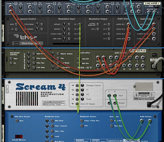
  7. We’re done with the front panel. Flip to the back of the rack, and let’s move on to routings. First, route the NN-XT’s 1/L and 2/R to the Audio In 1 and Audio In 2 on the Thor Audio Inputs, respectively. Then route the 1 Mono/Left and 2 Right from the Thor’s audio outputs to Channel 1 on the Line Mixer (left and Right, respectively). This sets up the audio to be heard. Now comes the Auto CV magic.
  8. In order for Auto CV to work, the Scream needs to have a sound source fed into it. So connect the Dr.Rex L & R audio outputs into the Scream Audio Inputs (L and R, respectively). Then connect the Auto CV output from the Scream unit into the CV 1 Modulation input on Thor.
  9. Auto CV routing to follow the Rex Audio file via CV
    Auto CV routing to follow the Rex Audio file via CV
  10. Flip the rack around and let’s set up the Thor Modulation Bus Routing Section (MBRS). Enter the following parameters on the left side of the bus:

    CV In 1: 66 > DelFBack

    CV In 1: 66 > Del ModAmt

    Enter the following parameters on the right side of the bus (just to keep things simple for now):

    Audio In1: 100 > Filt3 L.In

    Audio In2: 100 > Filt3 R.In

  11. The MBRS settings in Thor
    The MBRS settings in Thor
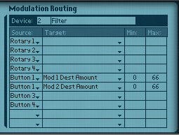
  12. With this setup, the Auto CV is affecting the Thor Delay Feedback and Delay Modulation Amount. To hear what the Scream is actually doing, we can set up a Combinator switch on button 1. So click the Show Programmer button on the Combinator, and click the Thor in the Device section of the programmer. Enter the following two lines in the Modulation Routing section:

    Button 1 > Mod 1 Dest Amount: 0 / 66

    Button 1 > Mod 2 Dest Amount: 0 / 66

    Programmer Modulation Routing in the Combinator
    Programmer Modulation Routing in the Combinator
  13. Now set up a Matrix to play a simple pattern using the Combinator. Turn Button 1 on to hear the Auto CV affecting the Delay. Turn it off to hear the unaffected Delay. Note that you need to have the Dr. Rex receive notes in order to have it send audio into the Scream device. By setting up the Matrix to sequence the combinator, the matrix ends up playing the Dr. Rex. So you’re all set. Alternately, if you don’t want the matrix sequencing the Combinator, you can always copy the Rex notes to its sequencer track so that the Dr. Rex is played via the main sequencer. The point is, the Dr. Rex needs to be active.

What’s happening is the Dr.Rex loop is converted to CV, and this CV is used to affect the Thor Delay. It’s a simple but powerful setup. And you don’t have to limit yourself to affect Thor parameters. I only used this as an example. You run any audio source through the Scream and then use the Auto CV to affect any other CV parameter. Also, since the Scream is not generating any audio output, it doesn’t affect the mix in any other way than a simple CV conversion (or more technically, a CV envelope follower).

Switching CV sources

Not to be one to leave well enough alone, here’s a way to extend the Auto CV idea above and have the ability to switch between two different Rex Files (2 CV sources) using the Thor. The parameters affected are the same (Delay Feedback and Delay Modulation Amount), but the Rex file used to affect the delay can be switched. Here’s how you do it:

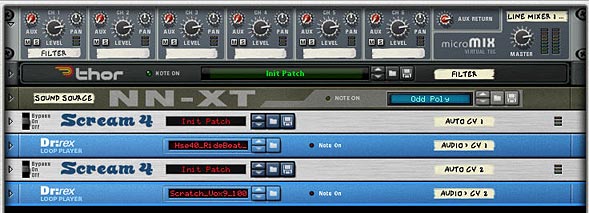
  1. Building upon the above example, at the bottom of the Combinator stack, holding Shift down, let’s add another Scream and Dr. Rex.
  2. Next, turn off the Damage parameter in the second Scream. Also, add a different loop into the second Dr.Rex device.
  3. The front panel with two scream and 2 Dr. Rex devices
    The front panel with two scream and 2 Dr. Rex devices
  4. Flip the rack to the back, and send the Audio from the Second Dr.Rex to the Second Scream, and send the Auto CV output from the second Scream to the CV 2 Modulation input on the Thor.
  5. Now we’ll have to set up Thor to also accept the second Dr.Rex CV source. In the MBRS section, enter the following:

    CV In 2: 66 > DelFBack

    CV In 2: 66 > Del ModAmt

  6. The MBRS settings in Thor
    The MBRS settings in Thor
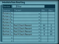
  7. Finally we need to use the Combinator button 1 as a switcher between the two CV sources. So in the Combinator’s Modulation Routing section, enter the following:

    Button 1 > Mod 1 Dest Amount: 66 / 0

    Button 1 > Mod 2 Dest Amount: 66 / 0

    Button 1 > Mod 3 Dest Amount: 0 / 66

    Button 1 > Mod 4 Dest Amount: 0 / 66

    Programming the Modulation Routings in the Combinator
    Programming the Modulation Routings in the Combinator

With this setup, Button 1 on the Combinator is used to switch between the 2 Scream CV sources (which in turn comes from the two Dr.Rex devices). Leaving button 1 off uses the first Scream device. Turning the button on turns off the first Scream CV source, and turns on the second Scream CV source. Note: it’s not actually the Scream that is turning off. We’re just bringing the amounts down to zero on the Thor programmer panel, which has the same effect.

It should also be noted that you can program a Rotary on the Combinator to cross-fade between the two CV sources, if you wish to have a fading effect between the two. Where you take this idea is really up to you.

Using Thor as an Audio/CV converter

Let’s say you don’t want to use the Scream, and instead want to use Thor as a “Auto CV output” or CV envelope follower. Here’s how you set that up.

  1. Starting from scratch, Create a Combinator and a 6:2 Line Mixer. Then holding shift down, create in order a Thor, NN-XT, and Dr.Rex device.
  2. Click the Show Programmer button in Thor, and turn off Oscillator 1, Bypass Filter 1, and click the “1” button next to the Filter 1 slot. Add a Low Pass Ladder Filter in the Filter 3 slot. Finally, click the Delay button to turn on the Global Delay.
  3. In the NN-XT open up the patch browser and navigate to the Factory Soundbank. Go to the NN-XT Sampler Patches > Synth Poly and open the Odd Poly patch.
  4. In the Dr.Rex device, open the Patch browser and in the Factory Soundbank, nagivate to Dr Rex Drum Loops and load the Hse40_RideBeat_130)eLAB.rx2 patch.
  5. We’re done with the front panel. Flip to the back of the rack, and let’s move on to routings. First, route the NN-XT’s 1/L and 2/R to the Audio In 1 and Audio In 2 on the Thor Audio Inputs, respectively. Then route the 1 Mono/Left and 2 Right from the Thor’s audio outputs to Channel 1 on the Line Mixer (left and Right, respectively).
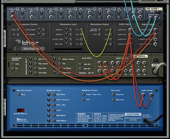
  6. This time, connect the Dr.Rex L & R audio outputs into Thor’s Audio Inputs (3 and 4, respectively). Then connect the CV 1 output to the CV 1 Modulation input, both input and output are on Thor, so yes you can route a CV out on Thor to a CV in on the same Thor.
  7. The back of the rack - routing Thor to work as an Auto CV envelope follower
    The back of the rack - routing Thor to work as an Auto CV envelope follower
  8. Flip the rack around and let’s set up the Thor Modulation Bus Routing Section (MBRS). Enter the following parameters on the left side of the bus:

    CV In 1: 66 > DelFBack

    CV In 1: 66 > Del ModAmt

    Enter the following parameters on the right side of the bus:

    Audio In1: 100 > Filt3 L.In

    Audio In2: 100 > Filt3 R.In

    Audio In3: 100 > CV Out1

    Audio In4: 100 > CV Out1

    The MBRS settings in Thor
    The MBRS settings in Thor

With this setup, the Auto CV is contained within Thor. The Thor is using the Audio from the Dr.Rex directly, and then converting the Audio source into a CV signal which is then sent back into Thor to affect the Delay Feedback and Delay Modulation Amount.

One note here: if you test out the sounds from the Thor CV setup versus the Scream CV setup, you’ll notice that the Thor CV is much smoother. I’m not sure why that is. It may be a difference in the way I’ve routed things, or a difference in how the Scream handles the Auto CV output feature. But there is definitely a difference in sound. Of course this could be pilot error and I may not have the connections set up correctly. I admit my mistakes all the time. But at least it gets you pretty close.

So any other ideas you have for using the Auto CV output on the Scream device or setting up Thor to convert an Audio signal into a CV signal? This is a very basic example, but it opens up a lot of potential with other sound sources / CV destinations. For example, if you have a CV destination that you want to track to the lead vocals in a song, you can do it easily. So what other possibilities are out there?