This article is not so much a creative experience as it is a basic concept and educational tutorial about how to create bypasses for your effect Combinators. You can use a bypass to enable the sound travelling through the effects processor to play while the effects are turned off, and then allow the effect to affect the sound when they are turned on. In essence, it’s a way to build your Combinators so that they can be more flexible, and still allow sound to pass through; letting you decide when you want the effects built inside them to take hold of your sound.
This may be old hat for many of you reading here, but I’ve had a few requests for some explanations on how to split signals and create chained effects. So I thought I would put together a little piece on some different bypassing methods, since that’s vital to the core of creating multi-FX processors.
You can download the project files here: Bypass-examples. This contains a few examples of different methods you can use to Bypass effects inside a Combinator. The files are all done in Reason 5, though you can still use them if you have Reason 4 as well. This zip file also includes updated versions of the 3 Key FluX FX processors I created for a recent article. This updated version allows you to still hear the unprocessed audio signal going through the Combinator when keys are not pressed. Read on to see how I set that up.
Why would you need a bypass if the Combinator already has an Enable On/Off/Bypass switch, as well as an “Enable all Effects” button. The answer is simple. The Enable switch can click and pop if you automate it or use it while the sound is running. For this reason, I never ever under any circumstances use it. Well, okay, I do use it the odd time, but only in a situation where I’ll either keep it on, off, or bypassed the entire time the song or track is playing. I never automate it to change during a track or song. If you do, you can have undesired “pop” consequences.
As for the “Bypass all effects” and “Run Pattern Devices” buttons on the front of the Combinator, the main problem with those is the lack of automation ability. Since you can’t automate them, you’re limited in how you can use them or set them up inside your track. And why limit yourself to a bypass that can’t be automated? So while these buttons are good for previewing sounds, and getting things to run on and off while I’m creating patches or testing patches, they have very little practical use for me when I’m building a song.
So here are some of the methods I use to create an FX bypass.
The Basic Button-based Bypass (say that ten times fast).
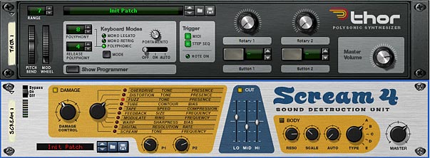
This method is probably one of the easiest and simplest of all bypasses. It allows you to build one yourself using one of the programmable Combinator buttons. We’ll start with the premise that you have created a Combinator with a 6:2 Line Mixer, added a synth (I’ll use a Thor here, but any synth or sampler will do). Then I have a Matrix playing this Thor synth. Finally, I have a simple Scream distortion unit at the end of the chain, so that the Thor synth is running through a Scream algorithm to give it some bite. This is our effect unit. And this is what we’re going to bypass.
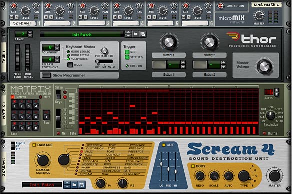
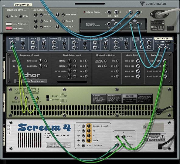
Now for the Bypass. Add a Spider audio merger/splitter between the Mixer and the Thor device. Flip the rack around (Tab) and connect the Thor left/right outputs into the Spider’s Splitter inputs. Then send one split pair out to the Line Mixer’s channel 2, and send another split pair output to the Scream input.
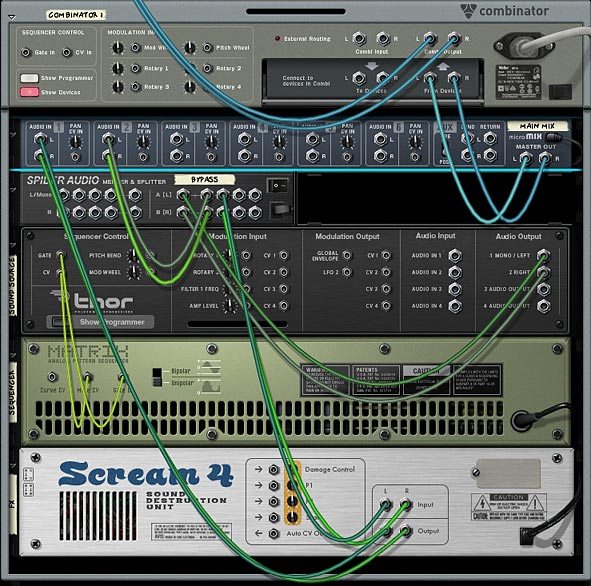
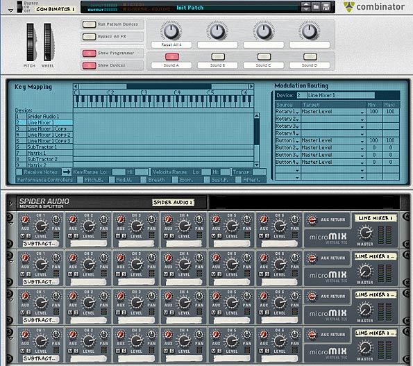
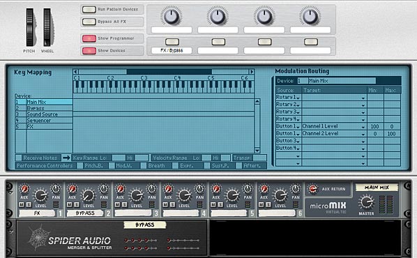
Next, flip back to the front of the Rack (Tab) and open up the Combinator programmer panel. Select the Line Mixer, and enter the following into the Modulation routing section:
Button 1 > Channel 1 Level : 100 / 0
Button 1 > Channel 2 Level : 0 / 100
This sets up Button 1 on the Combinator to switch between the two channels of the Line Mixer. If you play the sequence, you can bounce back between the FX-applied version of the sound (with the button disabled), and the bypassed (original unprocessed) version of the sound (with the button enabled). If you want to switch this around and have the bypassed version the default, just reverse the min/max amount values for Channels 1 & 2 in the Combinator’s Modulation Routing section, or else flip to the back of the rack and reverse the cable pairs going into Channels 1 & 2. That’s all there is to it.
Switching Between Three Values
This is all well and good, but there may be times that you want to switch between more than 2 parameters or channels. This can get a little more tricky, but is still relatively easy to work out. The trick involves creating a second 6:2 Line Mixer. I’ll show you what I mean below.
This idea came out of a user on the Reason forum who wanted a way to switch between Oscillator 1 and Oscillator 2, and then a Combo of both Oscillators together (1&2). I’ll use a different example here where I have a switch between 2 Scream algorithms (Scream 1 and Scream 2), and then another switch which bypasses both FX and gives you access to the original unprocessed sound. It’s the same type of idea, just implemented via FX instead of Oscillators. But if you want to read about the original question that was posted, here it is: https://www.propellerheads.se/forum/showthread.php?t=139636.
The way you do this is to first set up all the various parameters (or effects devices) to create the two different sounds. Working off the original “button-based” example above, we’ll add another Scream device below the first Scream unit (hold down Shift while you create the device, so that it’s not auto-routed). Send a new split pair from the original Spider, and have that going into the input on this “Scream 2” device.
Then create a new 6:2 Line Mixer beneath the first Line Mixer. Set up both line mixers with the following routings:
Line Mixer 1 (Main Mix):
Channel 1: Left / Right input from Line Mixer 2 (below)
Channel 2: Left / Right input from one split pair of the Spider Audio Splitter.
Note: The main left / right output goes into the “From Devices” input on the Combinator.
Line Mixer 2 (FX Mix):
Channel 1: Left / Right input from Scream 1
Channel 2: Left / Right input from Scream 2
Note: The main left / right output go into Channel 1 on Line Mixer 1 (Main Mix).
In the Combinator programmer, enter the following settings for the Modulation Routing:
Line Mixer 1 (Main Mix):
Button 2 > Channel 1 Level : 100 / 0
Button 2 > Channel 2 Level : 0 / 100
Line Mixer 2 (Main Mix):
Button 1 > Channel 1 Level : 100 / 0
Button 1 > Channel 2 Level : 0 / 100
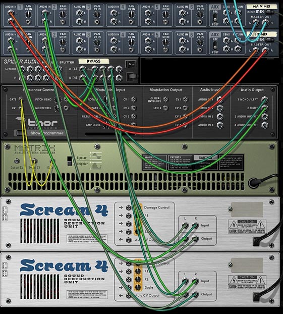
Now enable Button 1 and disable Button 2. This means the new Scream 2 device will be sounding. Note: you will first need to press each of the buttons once to “initialize” their settings. Enter some different settings on this new Scream device until you like what you hear (or load up a patch from the Factory Sound Bank).
Yes, there is a much more compact way of creating this type of scenario. It involves setting up only 2 Screams in series and then using the Combinator Modulation Routing section to enable / disable each Scream device (enabling / disabling each 3 parts of the Scream unit). But for the sake of showing how bypassing works, I’m not going to do it that way here.
With this setup, Button 1 acts as a switch between the 2 effects, and Button 2 acts as the bypass switch between those 2 effects and the original unprocessed sound. Cool right?
Bypassing FX that are on your Keys
There is another kind of bypass method that works well if you have your effects set up on keys. A perfect example of this is the “Key FluX FX Processor” Combinator I created a few articles ago. In those project files, I created a few different Combinators that were controlled by pressing the keys on your keyboard, but I failed to integrate a bypass method, so that you didn’t hear the original unprocessed sound when the keys weren’t being pressed. Essentially, you only heard a sound when the keys were pressed. So here’s a method you can use to create a bypass to hear the original unprocessed sound anytime the effects are not being played.
This method boils down to one thing: allowing the unprocessed sound to be heard when keys are not pressed. In other words, we need a way to tell Reason that when the MIDI gate is NOT triggered, let the sound pass through. When the MIDI gate IS triggered, let the effects be heard. We already have the latter part of this process set up in the patches by default. So we simply need to create a method for the former to work. Here’s how it’s done.
You need 3 things when creating this kind of bypass: A 6:2 Line Mixer, a Thor, and a Spider Audio Merger/Splitter. Add those into the Combinator. Take the left / right cable pair “To Devices” going from the Combinator into the Spider Splitter Left / Right input. Then send one split pair into Thor’s Audio In 1 & 2, and another split pair going out to the effects chain (in my Key FluX FX Processor patches, these cables would go into the first FX chain Spider Audio Merger / Splitter — to split the signal out to all the various keyed FX).
Then send the Left / Right audio output from Thor into the first channel of the 6:2 Line Mixer (in the image below, this is labelled “Bypass.” This Line Mixer’s second channel’s left / right input is coming from the end of the audio signal chain after all the effects. In other words, you need to send the final signal post FX processing into the second channel. This is the end of the audio line after the effects. The Line Mixer becomes the switcher, just like in the first example above, however, we’ve added an automatic component into the mix by adding the Thor device.
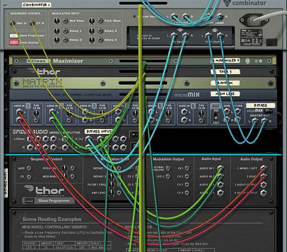
So what is this Thor device doing to the audio. Before it can do anything, you need give it an explanation of what you want it to do to your audio (which is much easier than explaining the Theory of Relativity to a third grader). In the Modulation Bus Routing Section (MBRS), enter the following:
Audio In1 : 100 > Audio Out1 : -100 > MIDI Gate
Audio In2 : 100 > Audio Out2 : -100 > MIDI Gate

There you have it. The negative MIDI gate values mean that the original unprocessed sound will shine through when the keys are NOT played. They will also cut the sound when the keys ARE played. In this case, since you have the effects loaded on the keys, the FX signal will take over and you’ll hear the effects processing the sounds while those keys are played.
It’s important to note that negative values are possible in the MBRS and can sometimes be preferred over positive values. I say this because many beginners who are new to Reason may not be aware of how negative values can be beneficial. Case in point above. Also don’t forget you can program Mod Bus Amount and Scale values inside the Combinator’s Modulation Routing section (to switch values using a Rotary or Button). And last but not least, you can automate Amount/Scale value changes directly in the main sequencer. So you have lots of possibilities here.
Lastly, since not all keys have effects mapped to them, you need to do one last thing. You need to map the key range of the Thor Bypass device to the same range as the keys that have effects on them. If you don’t do this, anytime you press a key that doesn’t have an effect loaded on it, you won’t hear any sound. This is because we’ve told Thor to cut out the sound on non-mapped keys. So open up the programmer, and select the “Bypass” Thor device. In the Key Mapping section of the Combinator, enter the proper Lo and Hi Key Range (near the bottom in the image below).
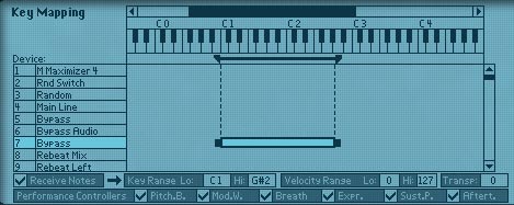
Note: Since you can’t map non-contiguous regions (two separate regions with a space between the two), you need to ensure your effects are mapped to consecutive keys along the keyboard. You can’t, for example, have A1 and A2 mapped to 2 different effects without any effects mapped to the keys in between A1 and A2. This just won’t work correctly.
Pretty simple right? That’s all there is to it.
So do you have any other interesting ways of bypassing signals in Reason. I can think of a few other innovative ways to do it using CV as well. But this should at least get you started when you begin creating your own effects devices inside a Combinator. If you have any other ideas, please share them with the group. It’s always good to get more than just my own opinion on the matter. Especially since there are so many talented Reason users out there. Until next time, have fun playing inside Reason!


