I’m obsessed with figuring out solutions to problems. One problem I recently encountered when I was putting together some files for the Alias8 PDF Guide, was trying to get the Alias8 Rack Extension Fader to double for a second control. I wanted to be able to use it to adjust two different parameters (let’s say Amplitude and Pitch of a SubTractor). The idea and thought process behind it is pretty easy. You adjust the Amplitude by moving the Fader, then click a button, and the Fader switches to adjust the Pitch. Click the same button again, and it goes back to controlling the Amplitude.
I’m obsessed with figuring out solutions to problems. One problem I recently encountered when I was putting together some files for the Alias8 PDF Guide, was trying to get the Alias8 Rack Extension Fader to double for a second control. I wanted to be able to use it to adjust two different parameters (let’s say Amplitude and Pitch of a SubTractor). The idea and thought process behind it is pretty easy. You adjust the Amplitude by moving the Fader, then click a button, and the Fader switches to adjust the Pitch. Click the same button again, and it goes back to controlling the Amplitude.
You can download the example files here: Alias8-Multi-Function-Fader. There are two Reason documents (.reason) and two Combinators (.cmb), which are explained below. The files will work in Reason 6.5 and above. To use them, you will also need the Alias8 CV Controller Rack Extension, which is available in the Propellerhead Rack Extension shop. To use, open up the file and go into the Combinator. Press the “Run Pattern Devices” on the Combinator, or press “Play” on the Matrix. The Matrix is used to gate the Subtractor, and is only used as an example so you can hear something when you tweak the Fader. A more comprehensive explanation is provided below.
To start, what I found is that you can’t completely get this type of functionality to work. Not completely. BUT, here are two ideas that get you pretty close.
1 Control with 2 Functions (V.2).reason / F1 2-Function Control (V.2).cmb Files:
I’m starting backwards here, because this was actually the second idea I had (hence, this is Version 2 in the filenames above). This idea uses two toggle buttons, one for Amp and the other for Pitch. Then, with the proper CV routing and an additional Thor to process the CV, you can map both parameters to the Fader. Click the first Toggle, and the Fader will control the amplitude. Click the Second Toggle, and it switches to control the Pitch. When the Amp toggle is off, you adjust the amplitude. Then click the Toggle button on, and the Amp level is held at the current Fader position. Then click the Pitch Toggle off, and the same Fader now controls the Pitch. Click the Pitch toggle on, and the Pitch is held at the current Fader position. The drawback is that you have to have both Toggle Buttons on to start with, and you can’t turn off both of them, since this would screw up the functionality. One of the buttons always has to be “On.” To get it “set” right again, you need to turn on both Toggles, then, turn one of them off and use the Fader. Sounds confusing, I know. But it’s the most efficient way I’ve found to set it up, as it only uses two Toggle Buttons (aside from the Fader).
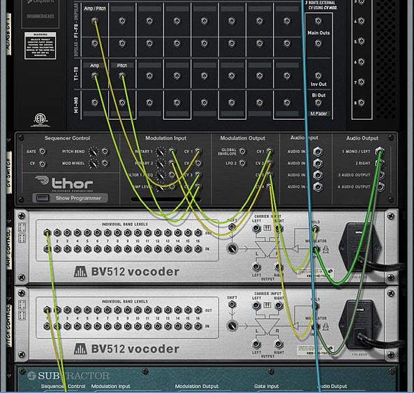
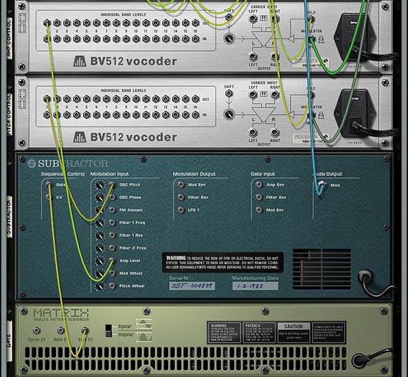
The Back of the rack for the “Version 2” example that uses 2 Toggles to switch Fader Parameters and simultaneously “Hold” the CV values via the BV512 devices.The CV routings from the BV512 into the SubTractor (destination parameters). The Matrix is there simply to “Gate” the SubTractor, so you can hear something and test out the Fader.The settings for the Modulation Bus Routing Section in Thor.
1 Control with 2 Functions (V.1).reason / F1 2-Function Control (V.1).cmb Files:
This next idea uses three additional buttons (aside from the Fader). The two Toggle Buttons act as the Amp / Pitch selection (as above), but a Momentary Button is used to switch between the two Fader states. The benefit of doing it this way is that you can’t screw up the functionality of the Fader in any way. The two Toggle Buttons act to “Hold” or “Freeze” the Level’s position for the selected parameter. The selection of which parameter the Fader controls is determined by the Momentary button. While I think this is a better method in some respects, it suffers from one disadvantage: You can’t tell which parameter is selected via the Momentary Button. There’s no real visual indication to tell you which of the two parameters are selected. This isn’t a big concern when you have only two parameters switched via the Momentary Button, but if you have several parameters you’re cycling through on that Button, things will get confusing quickly (though you could add a visual indicator with the DDL-1 or BV512 Vocoder, but it’s still not perfect – if interested in how this works, see the Kong FX Chain Builder tutorial where I discuss it at the bottom of the page).
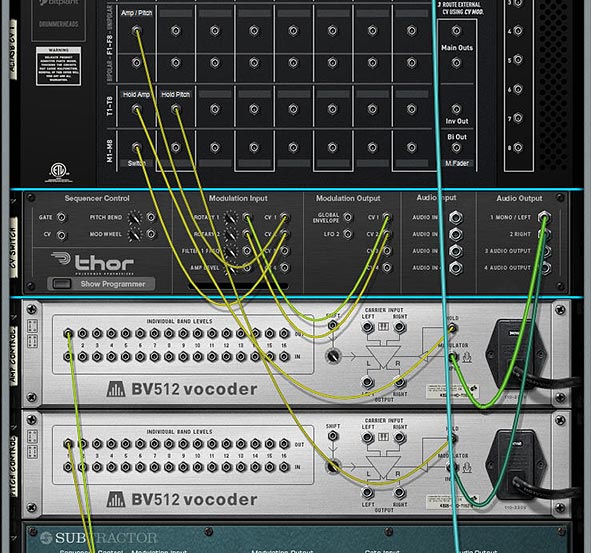
The Back of the Rack for the “Version 1” example that uses 1 Momentary Button to switch Fader parameters, and 2 Toggle buttons that “Hold” the CV values of the Fader via the BV512 devices. Note that the CV coming from the BV512 devices are routed into the SubTractor in the same way as the “Version 2” example (Refer to that image further up in this post).The settings for the Modulation Bus Routing Section in Thor.
How Does It Work?
The engine of this CV trick is the Thor device. What’s happening is that you are sending the CV value from the Fader into Thor, converting that CV value to Audio, then sending it through the BV512, where it gets converted back to a CV value that is sent out by Band 1 to control the SubTractor parameter (Amp or Pitch). The reason you need to convert it to Audio is because the BV512 Modulation input can be “held” — this allows you to “hold” the Fader value via the Toggle buttons on the Alias8. Note that this is also useful for a lot of other things because it allows you to “Freeze” any CV value in place (for instance, you could freeze the value of an LFO at any time by mapping the “Hold” button to a Combinator button, but that’s going a bit off tangent). There are 2 different BV512 devices because you need to be able to “Hold” each parameter you want to control with the Fader.
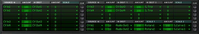
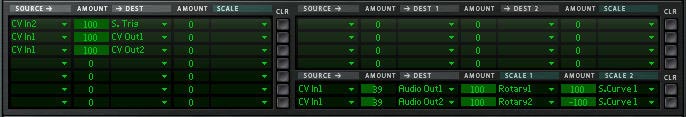
Another thing to keep in mind is the CV amount value of 39 in the Modulation Bus Routing Section on the front of Thor. This seems to be the correct value to correctly scale the “CV > Audio” conversion going out from Thor to the BV512 Vocoder. Note that the Rotary is used to Scale this “CV > Audio” conversion, and then the Fader value is going into Thor and modulating the Rotary, which in turn modifies the CV value being sent into the BV512 device. It seemed like the easiest way to set it all up, and the other benefit is that it doesn’t use any routings or mappings in the Combinator device itself.
A Few Additional Notes:
The value sent to the Fader seems to be Scalar, not Linear. Anyone who knows how the CV value can be sent to the Fader in a Linear way, please let me know.
I also would have loved to have one Toggle or one Momentary button switch between the two Fader parameters (keeping everything in one column in the Alias8), but I honestly don’t think this can be done. However, if you figure out a way, please let me know.
Even though this concept creates a multi-function Fader, there’s nothing saying you can’t set it up on a Rotary control instead, to produce a multi-function Rotary.
Why is this an important concept? Because it extends the functionality of a single Control on the Alias8, and the Alias8 device itself. For example, with a little thinking, you could create 8 different controls on 4 of the Alias 8 Faders, and still have 4 Free faders left over for more tweaking. Or have all the Toggle Buttons switch 8 different destination parameter controls on a single Fader, and free up the other 7 Faders for more tweaking.
Update
Eric Kloeckner was kind enough to expand on this idea and improve upon the above design. He managed to put the whole setup on a single Toggle button to switch the operation of the Fader between the two modulations. It solves the need for having two separate toggle buttons to drive the two different parameters.
I then took his design and tweaked it a little to make it as straightforward as possible. The concept uses 2 Thors to control the Toggle switch. This, in turn switches the Fader between the two modulation controls. The only downside is that you have to first “initialize” it by pressing the Toggle button at least once. But this is a huge improvement. And my thanks goes to Eric for finding a solution to one of the problems that was bugging me. Download the Files here: Alias8-Multi-Function-Fader-v2. There are two files in this zip:
Example File Combinator: Press play, and then toggle between adjusting the Pitch and the Level using Fader 1 on the Alias8.
Template File: Use the Output A / Output B spiders to send CV values to target multiple parameters as you wish. “A” parameters are adjusted when the toggle button is “off” and “B” parameters are adjusted when the toggle button is “on.” Use this setup to create a template where all 8 faders can have multiple-functions if you like.
Note: There’s still a slight discrepancy between the CV input & output. In other words, it’s still not 100% Fader value CV : Destination value CV. You’ll still get slightly off results (where moving the fader on a single CV value will bump up the Output CV value by a value of “1,”). However, this is very slight, and shouldn’t be a problem in most cases.
That’s it for now. Don’t forget that the Alias8 PDF Guide I put together contains many other creative ideas for this Rack Extension, so check it out as well. Happy Reasoning!
In this next installment of the Reason 101 guide to creating better patches, I’m going to focus on setting up the Wheels, Rotaries, and Buttons in Thor, and discuss some creative ways you can implement your modulations. Hopefully this will provide you with some further inspiration when you’re building your sounds.
In this next installment of the Reason 101 guide to creating better patches, I’m going to focus on setting up the Wheels, Rotaries, and Buttons in Thor, and discuss some creative ways you can implement your modulations. Hopefully this will provide you with some further inspiration when you’re building your sounds.
The Pitch Bend & Mod Wheels, and four assignable controls (two Rotaries & two Buttons) in Thor's Controller Panel
The Pitch Bend Wheel
The Pitch Bend Wheel is a bipolar (it goes both positive and negative) bend wheel that is normally used to apply pitch modulation to the sound. The bend modulates the pitch smoothly upward or downward by a specific set of semitones (as outlined in the “Range” field — Thor can go from 0-24 semitones for a maximum two octave range). In terms of MIDI data, the Pitch Wheel goes from a value of -8,192 to 8,191. In the majority of circumstances, you’ll want the Pitch Wheel to modulate the note value (pitch) of the sound, and this is the default behavior (meaning, you don’t need to set anything up in the MBRS to use it to control the Pitch of your patch – however, you DO need to have the KBD knob in the Oscillators tracking the keyboard for the Pitch Wheel to have an effect on pitch – the knob should be set at a position other than zero, and usually set fully right). However, there are cases where pitch is either not necessary to the sound you are developing, or you may simply wish to modulate something other than pitch. You can easily do this in Thor.
A good example where Pitch may not be necessary is if you are using the Step Sequencer to set up a specific sequence to play the Thor patch with specific note values in mind, or if you are restricting your patch to play at specific pitches, and don’t want the user changing the pitch on you. If that’s the case, you set up the sequence using the Note value in the step sequencer. Another example might be if you have a drum sound that doesn’t require pitching. Though, I have to admit, it’s pretty rare that I program something other than Pitch on the Pitch Wheel.
If you are NOT going to use the Pitch Wheel to modulate the Pitch parameter in Thor, you’ll need to do the following:
First, if your patch is pitch-capable, meaning you are tracking pitch along the keyboard (using the KBD knob set fully right in the oscillator sections), you can force the Pitch Wheel to be non-responsive to the pitch by reducing the Pitch Wheel range to zero (0).
Next, I would strongly advise you to assign something to the Pitch Wheel using the MBRS. Remember that most everyone that has a Piano, Organ, or MIDI controller will have a Pitch Wheel, and to leave it unassigned is going to make the musician wonder why nothing is happening when they use it. And this article is all about making better patches right? So assign something to the Pitch Wheel.
The Pitch Bend and Mod Wheel options in the MBRS under the "Performance" submenu. They can be used as Modulation Sources or Scales.
When you assign a parameter to the Pitch Wheel, remember that the wheel is bipolar. This makes it a little more tricky when assigning modulation parameters. If the destination you are modulating is already bipolar in nature, it’s relatively straightforward. The most obvious parameter I can think of is the Amp > Pan parameter. By default, the Amp Pan knob in Thor’s voice section is centered in the middle of the stereo field. If you add the following line in the MBRS:
Pitch Bend : -100 > Amp Pan
Then, when the Pitch Wheel is pushed upward, the sound is panned left. When the Pitch Wheel is pushed downward, the sound is panned right. As with all MBRS settings, you can reverse this relationship, as follows:
Pitch Bend : 100 > Amp Pan
Then, when the Pitch Wheel is pushed upward, the sound is panned right. When the Pitch Wheel is pushed downward, the sound is panned left.
The default position of the Pitch Wheel is the same as the position of your Amp Pan knob (centered in the stereo field). If you were to change the position of the Pan knob to be more left or right, the Pitch Wheel will have a different “starting” position, based on this pan knob’s position.
So now, if you want to use the Pitch Wheel as a source to modulate a unipolar destination (Amp Gain, for example), you need to think a little harder about your starting position for the gain knob. If you turn the amp gain knob all the way down (fully left), and enter the following in the MBRS:
Pitch Bend : 75 > Amp Gain
The Pitch Wheel will turn the Gain up by 75% in volume when you push the wheel upward. But nothing will happen when you push the wheel downward. In order to have some movement in both directions, you need to turn your unipolar destination control (the Amp Gain knob in this example) to a more “middle” starting location. This is because the Pitch Wheel is bipolar and can move in two different directions (up or down). The Amount in the MBRS which is assigned between the Pitch Wheel and the destination determines how much the destination is modulated “in both directions.” Positive or Negative amount values simply determine which direction the modulation occurs. Put another way:
Positive Mod Amount = Pitch Wheel up (moves Positive from the destination’s start position); Pitch Wheel down (moves Negative from the destination’s start position).
Negative Mod Amount = Pitch Wheel up (moves Negative from the destination’s start position); Pitch Wheel down (moves Positive from the destination’s start position).
Of course, there’s nothing stopping you from combining effects. You could raise the Pitch Wheel range back up to 2 (whole tone; major second), 4 (major third), 7 (perfect fifth) or 12 (Octave), and combine the Pitch bend with the Pan bend. Or any other combination of Thor destination parameters you like.
In the physical world, the Pitch Wheel’s default starting position is in the middle (in the virtual world, this is a bipolar value of zero), and you can move the Pitch Wheel up (positive) or down (negative). If you move the wheel all the way up or down, and let go of the wheel, an internal spring will send it back to the zero position. In Reason, the same thing happens. If you move the Pitch Wheel up with the mouse, for example, and let it go, the wheel reverts back to the default zero position. For this reason, you cannot save the Pitch Wheel in a position other than zero when saving your patch.
Of course, if you are saving the song file, there is a very simple workaround for saving the Pitch Bend at a location other than the default zero. Simply add an automation lane in the main sequencer in your song, and draw the automation at any value you like. Then save the song. The automation forces the Pitch Wheel to be saved at a location other than zero. This is probably never necessary though, if in fact you are using the Pitch Wheel to control Note Pitch, because you can always just change the pitch of your Oscillators in Thor. But this could be a valid approach if you have some other modulations set up on the Pitch Wheel and need to have the Wheel start at a value other than zero.
The Modulation Wheel
The Mod Wheel is a unipolar (it goes positive only) wheel that is used mainly for Vibrato, Tremolo, or both. From a MIDI standpoint, it goes from a value of zero (0) to 127. However, as with the Pitch Wheel, the Mod Wheel can be used to modulate any parameters you like in Thor. By default, the Mod Wheel always starts from a position of zero as well, but it does not “spring” back to zero if you raise it and let go of it. For example, if you move the mod wheel up to a value of 70, then save the patch. The next time you open the patch, the Mod Wheel will “start” at zero. But if you are performing while using the Mod Wheel, you can raise it to 70 and let go. It will still remain at 70 until you stop the song. The value setting of 70 is not retained from session to session, but is retained while you are performing. In the world of physical controllers, the Mod Wheel has no spring.
Of course, there’s nothing preventing you from drawing an automation lane for the Mod Wheel in the main sequencer in Reason, and assigning a different value, then saving the Reason song file (as explained in the Pitch Wheel note above).
Since the Mod wheel is common to about 99% of all keyboards, both traditional piano instruments and MIDI Keyboard controllers, and Rotaries / Buttons are much less common, I usually ensure that the modulation that is most important for the patch is applied to the Mod Wheel. Less important modulations should be placed on the Rotaries and Buttons. Aside from that, if your patch calls for Tremolo or Vibrato, the Mod Wheel is a good location for this, since it just “makes sense” for the musician to access these effects from the Mod Wheel.
It should also be noted that while the focus of this article series is using the front panel of Thor to modulate parameters and build better patches, you have several CV options on the back of Thor. These CV options can be used to control the Pitch and Mod Wheels, Rotaries, and Buttons of Thor (Note: Buttons have no direct CV inputs or outputs, but can be controlled by wrapping the Thor inside a Combinator and using the Combinator’s programmer).
User-Assignable Rotaries
The two Rotaries in Thor’s Controller panel can be used to modulate any parameters in Thor via the MBRS. Practically speaking, the Rotaries serve the same purpose as the Mod Wheel, except that it’s a knob instead of a wheel. There’s also one other difference: Rotaries can have a starting position anywhere between the left and right side of the dial. Something the Mod Wheel cannot do (the Mod Wheel always starts at a position of zero, remember). I typically use Rotaries to create variations in the Timbre of the patch, frequency, FM applications between Oscillators and filters, Mixing between Oscillators, Crossover effects (see my Thor Crossfading Techniques for some ideas on this), Delay or Chorus levels, or any other aspects of the patch that could prove useful.
The two Rotaries and Buttons in the MBRS under the "Modifiers" submenu. They can be used as Modulation Sources or Scales.
If the patch is a drum patch, I sometimes will put the delay time on the Rotary and then have the Delay On / Off assigned to a button under that Rotary. This can produce rolls for your drums. Of course, these are all just idea springboards. You can assign any source parameter to modulate any destination parameter in Thor, and so outlining them all is not practical in a tutorial such as this. The key here is your imagination and creativity.
One piece of advice though: If you are assigning modulations to the Rotary (as a source), try to assign more than one destination in Thor. For example, assigning Rotary 1 to control the Filter Frequency will at least make your patch “good” because you at least have Rotary 1 doing something. But assigning Rotary 1 to raise Filter 1 Frequency while reducing Filter 1 Resonance, or assigning Rotary 1 to Raise Filter 1 Frequency while reducing Filter 2 Frequency and at the same time raising the AM amount between two oscillators can raise your sound design idea from “good” to “great.” I’m not saying that every Rotary and Button should have more than one assignment, but often times, you can create more subtle variation in the sound, or create something that is much more dynamic, responsive, and unique by layering your modulations. This advice goes not just for the Rotaries, but any modulations you develop inside your patch. Always look at ways you can improve upon what you’ve done. And always try lots of experimentation. Sometimes you’ll come across an unexpected result that can improve your patch.
User-Assignable Buttons
The two Buttons in Thor’s Controller panel can be used to modulate any parameters in Thor via the MBRS. Because the buttons can contain only two positions, this makes them the perfect place to create on/off modulations. However, it would be careless to think that these controls are simplistic. You can create some amazing variety within a two-setting limit. For example, think about creating two distinct instruments within a single Thor patch. Or even four, if you want to be so bold and use two different buttons. These are what I call “Hybrid” patches. Here is one example:
First, you can easily change a Synth sound into a Pad sound using little more than the Attack and Release of the Amp Envelope. Leave the Decay and Sustain levels somewhere in the middle or higher up, and when the Attack and Release are short, the patch can sound like a synth. Modulate the Attack and Release higher up, and the synth will take on a pad-like quality. In the MBRS, the settings would go something like this:
Note that you can set up two destinations in the top right MBRS row, which sets up a shorthand to use one source to modulate two different parameters. This uses one single row for two modulations.
Try creating a Bass / Synth hybrid or a Bass Drum / Snare Drum hybrid. Challenge yourself to come up with a few hybrid patches like this, just for the fun of it.
Some other modulations I usually place on the buttons are things like a one-stop Chorus or Delay on/off button. For example, if I’m putting the Chorus on a button, I first turn on the Chorus, then set up the Chorus parameters to specific settings that works with the patch I’m creating (Delay, Feedback, Rate, and Amount; but not the Dry/Wet knob). Once I have everything set up, turn the Dry/Wet knob completely off (turned fully left). Then in the MBRS, I would add the following line:
Button1 : [“X” Amount] > Chorus Dry/Wet
where “X Amount” is the amount you set up as you listen to the patch and play it back. Usually settings between 60-80 are a pretty good range, though it depends on the sound you’re going for.
Since you have turned off the Dry/Wet knob in the Chorus section, the Dry/Wet value is determined entirely with the MBRS setting you just entered. When the button is off, there is no Chorus. When the button is turned on, the Chorus you just set up is turned on. Simple and elegant.
Think about putting a Drum Roll on the button using Delay, or using the Shaper or FM between oscillators to create distortion. Or Frequency Wobbling for a bass. As with the Rotaries, the sky is the limit. Modulate, modulate, modulate.
Lastly, another reason I use Buttons is to reverse modulations around. I alluded to this when I was discussing Velocity in Part 2 of this series, but let’s look at it from another example. Let’s say you modulate your pitch upward using the Mod Envelope. You would first raise the Decay of the Mod Envelope, and then set up two lines in the MBRS as follows:
Mod Envelope : 30 > Osc1 Pitch : -100 > Button 1
Mod Envelope : -30 > Osc1 Pitch: 100 > Button 1
This means that when the button is off, the Decay of the Mod Envelope bends the pitch upward by an amount of “30” (noted by the first line in the MBRS). When the button is turned on, the same Decay of the Mod Envelope bends the pitch downward by an amount of “30” (noted by the second line in the MBRS). The button acts as a reversal of your modulation.
Button Key Triggers
One other really useful aspect of the buttons is the fact that you can assign a MIDI Key from your keyboard to turn the Button on and off. Use the arrows to the right of the Button (also called a “spin box” control) to select a key. Then as you play, use the Key that is assigned to that button to turn the button on. This works as a “Momentary Trigger,” meaning that the button will remain on as long as your key is pressed down on your keyboard, and turns off when you lift your finger off the key.
For example, if you set up the Chorus on a button as I outlined above. Then use C-2 as the key trigger, you can play your patch using any of the other keys, and press C-2 to hear the Chorus affecting the sound of your patch as you play. If you have set up the hybrid Synth/Pad patch that I outlined above, you could easily switch between the two timbres of the patch using a key trigger, and do all of this “Live” as you play. Great fun
Thor’s Built-in Tutorials & Mod Wheel Vibrato
If you flip to the back of the Thor device Programmer panel, you’ll see a lot of great tutorials that can be used as starting points. Let’s take a look at the first one, which sets up Vibrato on the Mod Wheel, and see if we can expand on it. This will also be a good excercise to show you how changing a few MBRS settings can extend the power of one simple concept: Vibrato, turning it into a Vibrato / Tremolo crossfade that can be turned on and off.
Vibrato tutorial on the back of the Thor Programmer panel, among many other useful tutorial ideas.
First, Let’s flip back to the front panel again and Initialize the Thor patch.
Enter the Mod Wheel Vibrato settings in the first row of the MBRS, as outlined in the above Thor tutorial.
Next, let’s set up Tremolo (change in volume) on the Mod Wheel to hear how that sounds instead of Vibrato. Just change the destination from “Osc1Pitch” to “Amp Gain.” And turn the amount between the Source and Destination up to around 66, so we can hear the effect better. That’s pretty easy stuff right?
Ok. Let’s take things a little further by creating a cross-over between Tremolo & Vibrato and place it on Rotary 1 instead of the Mod Wheel, by replacing the line we entered previously with the following two lines in the MBRS:
LFO 2 : 25 > Osc1 Pitch : -100 > Rotary 1
LFO 2 : 66 > Amp Gain : 100 > Rotary 1
This is a great way to use one Rotary to control the Vibrato & Tremolo effect of your patch, however, it means that the effect is always applied to the sound in your patch. There’s no way to turn the Vibrato & Tremolo “off.” To do this in a very clean way inside the Thor MBRS, you can utilize the “double-scaler” rows located in the bottom right part of Thor’s MBRS. Be sure to delete the above lines in the MBRS and replace them with the two lines shown below. Also don’t forget to label the Rotary 1 and Button 1 as shown below:
Using Rotary 1 to Crossover between Vibrato and Tremolo, then setting up Button 1 to turn the Vibrato/Tremolo on or off.
This process of adding a second scale to both lines allows us to scale our modulations with two different controls. Put another way, the pitch and amp gain are always controlled by Rotary 1 from left to right when Button 1 is on, but they are not controlled by Rotary 1 when Button 1 is off. With a little extra thought, and a few more MBRS assignments, you can use Rotary 1 to control something completely different when Button 1 is off as well. This way, Button 1 becomes a switch between the Vibrato/Tremolo effect AND something else. It also means that Rotary 1 will be modulating something inside your patch, whether Button 1 is On or Off. But I’ll let you take it from there and figure that one out on your own. If you’ve been following all these tutorials, that should be child’s play for you.
More Great Sound Design Ideas
The Props are putting on a really great video-based series centered around Sound Design, and they’ve been kind enough to post my articles on their Facebook page in conjunction with this series. So I wanted to return the favor and provide a link to check out their videos here (in the event you’ve been living under a rock and haven’t heard about them). You’ll learn a lot from each one of them. Check them all out in the following playlist:
So far, we’ve gone through the discussion of keeping Consistent levels, working with Performance parameters such as Velocity, Key Scaling, Aftertouch, and Wheel assignments; and dealing with the User-assignable Rotaries and Buttons. Along the way, I hope I’ve also given you a thorough introduction to the Modulation Bus Routing Section (MBRS) in Thor. In the next part, I’ll go through a few more examples to take what we’ve learned here and translate it into some patch design ideas and improvements to existing patches. More thoughts on all this later. In the meantime, tell me what you think of this series, and let me know if you have any ideas that have come out of these articles. As always, I’d love to hear from you. Happy music-making!
Since Ed’s Thor Shaper article, I’ve been thinking about how to use this information in real-world examples. One idea is to crossfade the Grain Samples in the Malstrom and another idea is to crossfade all 4 Thor filters to affect one sound source. Lots of fun!
Since Ed’s Thor Shaper article, I’ve been thinking about how to use this information in real-world examples. One thought came from a post I saw on the Props forum. Basically, the issue was that you can’t assign the Malstrom Grains to a Combinator Rotary to effectively switch between the 80+ Grain Samples. It’s pretty easy to assign and switch between Modulator waveforms using a Rotary, but not the actual samples in the Malstrom. So this got me thinking of how you could go about switching between these Samples. And truth be told, there’s probably some really obscure way to do it which uses Thor and some heavy CV connections. But here is something that might just inspire you and be the next best thing.
You can download the project zip file here: crossfading-malstroms-and-filters. This file contains 2 rns files with the Combinator setups explained below. One is a 16-Malstrom crossfader, and the other is a 4-way Thor filter crossfader. I would recommend you download them and open them up as you read. It will make things a little easier that way.
Crossfading 16 Malstrom Grain Samples
In this setup, I’m using 16 Malstrom devices and each device is sent to a Mixer Channel in two 14:2 Mixers. The CV from the various Thors are sent to the Mixer Levels, where the level trim knobs are pushed all the way right, and the Mixer channel Levels are set to zero. If you haven’t already seen Ed’s interesting and enlightening tutorial on the subject, you should read it here: Ed’s Thor Shaper Tutorial. It goes through using the Sine Wave Shaper in Thor to create a 4-way Crossfader. In this way, you can cross-fade between 4 different Malstroms. Each Malstrom’s Oscillator A is set to a different Sample.
Since you have 4 Rotaries, each Rotary is set to 4 Malstrom devices. Giving you a total of 16 different Oscillators. Also, since one or more oscillators will be playing at any one given time, I’ve set up each button on the Combinator to mute the specific series of Oscillators. Button/Rotary 1 affects the first group of 4 (Malstroms 1-4), Button/Rotary 2 affects the second group of 4 (Malstroms 5-8), and so on. Only 10 Malstroms should be applied to a single Mixer because you can only map 10 parameters from any one device to the Combinator, and you need all 10 channel mutes mapped to the various Combinator buttons.
To take this a step further, you could create 6 Combinators, which together would contain the full 82 Oscillator Samples used by the Malstrom. Then you could crossfade between any oscillator you like. The sweet spots for each of the rotaries are as follows:
0 = Oscillator 1 Full Level
42 = Oscillator 2 Full Level
85 = Oscillator 3 Full Level
127 = Oscillator 4 Full Level
Any integer between those values will provide a crossfade between the two Oscillators on either side of the value. This can be seen as a downside or an upside. If you want a pure switch between Oscillator 2 and 4 for example, you can automate the Rotary to go straight from 40 to 85 in your sequencer using a Rotary automation lane. In this sense, you can use the Rotary as a 4-way button switcher between each Oscillator.
On the downside, you couldn’t effectively crossfade between Oscillator 2 and Oscillator 6 (on Rotary 2) the way the current Combinator is set up. But if you Reorganize the way the buttons mute, you could effectively do this. I’m open to anyone who has any other suggestions on how this could be achieved. Another downside is that since a different Malstrom is used for each Oscillator, you’ll have to tweak the settings on each Malstrom to get exactly the sound you want. If you want to keep everything consistent between all Malstroms, you’ll have to do it through automation (the easiest way I think). Simply automate one parameter on the first Malstrom in the sequencer, and copy that automation clip into every other Malstrom’s automation lane. It’s a bit of a pain, but it will keep all Malstroms in line, if that’s what you want.
On the upside, since there are 16 different Malstroms, you can fine tune the sound of each of them separately. If you have all the mutes off, you can effectively crossfade between 4-8 Malstrom sounds/devices at once just by shifting the Rotaries around. This adds some very interesting Sound Layering potential.
As it stands, the first 16 Oscillators from the Malstrom are applied to the 4 Rotaries on the Combinator. As I said, you could build up a stack of 6 Combinators to include all the Malstrom Oscillators. In this way you can build up various sounds and switch between the various Oscillators. Does this help anyone out?
Crossfading all 4 Thor Filters, and then some. . .
Next, let’s take a look at how we can crossfade all of Thor’s filters to affect one synth sound. In this case, it’s fairly simple to set up. First, create a Combinator, and set up Ed’s 3 Sine Shaper Thor’s to handle the CV like the previous example (along with a 14:2 Mixer). Then create a Thor and load up a synth sound. Start off with something simple so that you can really hear the different filters affecting the sound. Then create a Spider Audio CV Merger / Splitter, and send the synth’s Left and Right Audio Outputs to the splitter’s inputs. Create 4 Thors underneath the splitter and send each of the 4 splits to these respective Thor’s Audio Inputs 1 and 2. Finally, send the 4 Thor’s Left and Right Audio Outputs to the first four 14:2 Mixer channels.
The setup with The Sine Shaper CV and Audio outputs from Thor into the MixerThe Thor Synth Audio being split and sent through the 4 Thor Filters
On the front of the Rack, add a Low Pass Ladder Filter in the first Thor’s Filter 3 Slot. The settings for this filter are shown in the image below. In addition, add the following into the Modulation Bus Routing System (MBRS):
Audio In1: 100 > Filt3 L.In
Audio In2: 100 > Filt3 R.In
The Low Pass Ladder Thor Filter settings on the front Panel
Enter the same settings in the other 3 Thors, but with different filters, so you have the State Variable filter in Thor 2, Comb filter in Thor 3, and Formant filter in Thor 4. While you’re at it, play around with the Global ADSR envelope so that it sounds to your liking for the 4 different filters. It’s ok if these settings are different for each filter. This will just make your sound more interesting. One thing I kept the same across all 4 Thor Filters is the FX section (Delay and Chorus). This way, when the filters are transitioned, the FX remain similar across the board.
Now let’s turn to our Combinator section and do some serious routings in the Mod Matrix. Here’s the settings you will need for each of the Thor Filters (they are the same for all 4, but must be applied to all 4):
Rotary 1 is reserved for the Filter Crossfade, so I’m not going to go over it here. You can see it in the Project File rns.
Rotary 2 > Filter 3 Freq: 0 / 127
Rotary 3 > Filter 3 Res: 0 / 127
Rotary 4 > Filter 3 Global Env Amount: 0 / 127
Button 1 > Delay On: 0 / 1
Button 2 > Delay Sync: 0 / 1
Button 3 > Chorus On: 0 / 1
Button 4 > Filter 3 Global Env Invert: 0 / 1
Mod.W > Filter 3 Drive: 50 / 127
The Combinator Mod Bus Routing settings for each of the Filters
Now, what’s happening is that the Mod Wheel controls the drive amount on each of the Filters, While Rotary 1 cross-fades all the filters. This is the main Rotary, and it has the same sweet spots as the previous Malstrom patch. Rotary 2 and 3 control the Frequency and Resonance of the filters, and Rotary 4 adjusts the Envelope of the filter. Button 4 inverts this envelope. The remaining buttons are left for the Delay, Delay Sync and Chorus. Since all the parameters are the same for all the filters, they all shift together. This can be a positive or a negative. You can’t individually set the filters, but at least they sound pretty good when transitioned. Depending on your ADSR settings for the Global Filter, the Envelope Rotary and Envelope Inversion Button may be different for each filter. But as I said before, this can add some nice variety to the sound.
Use this Combinator as a template for your own sounds. All you have to do is add your own patch into the Thor “Synth” or change the Thor “Synth” to any other Synth or Sampler device if you like. Then you’re in filter crossfading heaven.
A huge thanks to Ed for being the inspiration for these patches. Please let me know what you think and if you can think of any other applications that this crossfading technique can have, by all means share it with us. Until next time, have fun with these.