24 – A few No-Nonsense Tips

In this tutorial I’m going to outline some of my favorite quick tips that you can use when you find yourself in a bit of a bind with Reason. Hopefully these little tips open you up to a new way of thinking with the software, or else at least point you in the right direction if you get stumped.

In this tutorial I’m not going to outline any grandiose Combinator or showcase some majorly complex CV routing scheme (though I have a few interesting ones that I may show down the road). Instead, I’m going to outline just some of my favorite quick tips that you can use when you find yourself in a bit of a bind with Reason. Hopefully these little tips open you up to a new way of thinking with the software, or else at least point you into a direction in case you get stumped.

All of the tips below came out of a need I had to get out of jail with the software. In other words, I’d find myself at a standstill unable to go further because I’d locked myself in a hole. Here’s a few ways I found to get out and escape. I hope you find these tidbits useful.

Tip #1: Unison = Stereo (It’s not just big fat sound).

The first tip came out of a post I’d seen on the PUF (Propellerhead User Forum) entitled “Confessions.” In this post, a few people had stated that they never used the Unison device, and didn’t really understand what it was for. “I think it has something to do with fattening up the sound, but I don’t really use it and don’t really know what it’s for.” Fair enough. Here’s what I think:

Yes, it fattens up the sound. But it does more than that. For instance, take any monophonic sound device; The Subtractor and Thor come to mind. If you start playing either device, you can tell it sounds monophonic. In the case of Thor, you can do some clever things like add some Chorus and Delay. Perhaps in the Subtractor, you’ll add some ring modulation or FM synthesis, detune two oscillators together. But here’s the dilemma: you add a Stereo Imager after the device and nothing happens? Why?

This is because the Stereo Imager only works on Stereo audio, and since you have a device which is monophonic, nothing is going to happen. The simple fix: add a Unison device between the sound source and the Stereo Imager. Instantly, you’ve turned your sound into a Stereo audio pair going into the Stereo Imager, which can now effect the sound as you want (point of fact, it’s more of a faux stereo, but it works).

The unison device is there to “Stereo-ize” your monophonic sound. At the same time, it fattens the sound by creating multiple detuned voices out of the audio you send into it. Good enough!
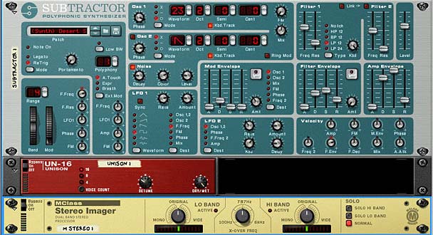
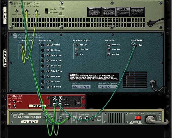
The front of the rack showing the Unison device creating Stereo out of Mono
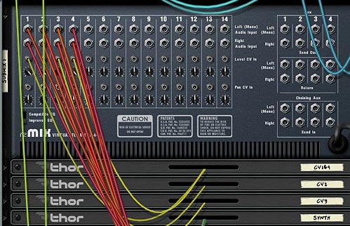
The back of the rack showing the Unison setup

Tip #2: Mixer Pan/Level CV automation is holding me back!

Ever automate the level and/or Pan info on your main mixer in Reason or Record and then realize you can’t alter it at all. For instance, if you send a Subtractor LFO to fully automate the level of your track, you end up unable to alter or change the level to fade it in or out right? Whatever is playing in a clip in your sequencer will be affected by the LFO as is. No fade ins, no fade outs, no changes along the way. Same goes for panning.

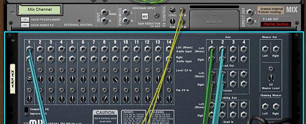
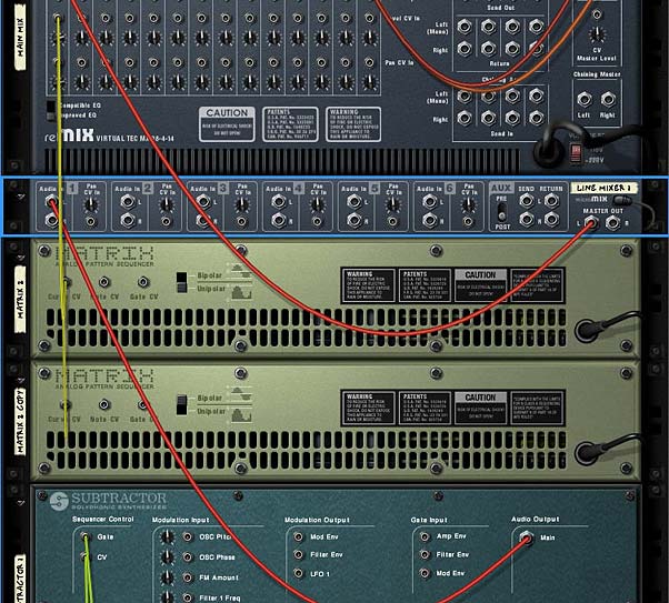
Here’s a simple tip to allow you to have both. And again it involves inserting a device between the sound source and the mixer. In this case, it’s another line mixer. Insert a 6:2 mixer between your main mixer and the sound source. Then flip the rack around and move the audio cables from the sound source into Channel 1 on the 6:2 line mixer. Then send some audio cables from the main output on the line mixer into the previous channel on the main mixer. Now you can flip back to the front again and right-click on the Channel 1 level knob, select “Edit Automation” and enter your fade-ins and fade-outs. You can also adjust your panning on this line mixer as well. This will affect the panning of the sound source before it gets sent into the main mixer where the CV is affecting the panning. In this case, the panning is combined together.
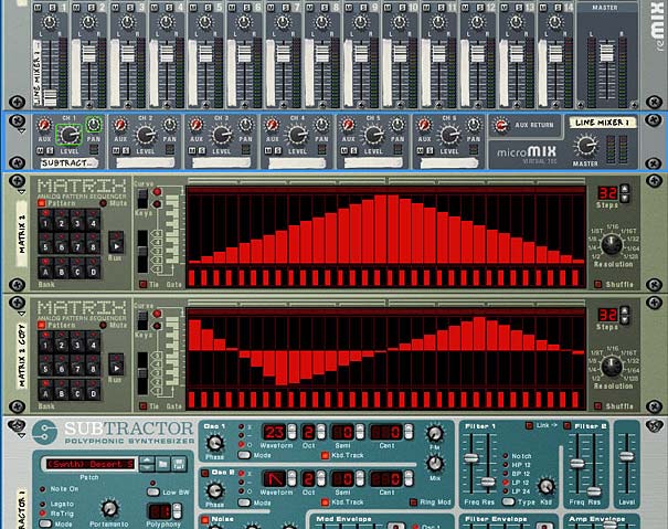
The front of the rack showing the Line Mixer inserted between the audio signal and main mixer.
The back of the rack showing the connections for the audio signal.

There you go. Total control over your mix, even when your mix is being controlled by CV.

Tip #3: While we’re on CV, don’t forget you can automate any CV trim knob on the back of any device

I discussed this tip in full here: #7 – Adjustable CV, but it bears repeating. If you want to control the trim pots for any CV connection (you know, the tiny knobs on the back of your devices into which you send the CV cables), simply insert a Thor device between the CV source and the CV destination. Route the CV into the CV in 1 within Thor, and send it out from CV out 1. Then in the modualtion Bus Routing Section of Thor (MBRS), use CVin1 as a source and CVout1 as a destination. Enter 100 as an Amount, and then use Thor’s Rotary 1 as a Scale (also with an amount of 100). Put everything (source/destination devices as well as the Thor “CV Pass-Through” device) into a Combinator, and program the Combinator’s Rotary 1 to adjust Thor’s Rotary 1.

This means that you’re adjusting the Scale amount value using the Combinator Rotary 1. Essentially, this will have the same effect of adjusting your CV trim pot. Sounds complicated, but it’s really quite simple.

Tip #4: Damn it, there’s no CV connection. But I want to automate it with an LFO!

Enter the Combinator to the rescue. For this trick to work, you have a device which has a parameter you want to affect with an LFO (or any other mod envelope or anything you like) and the device with the LFO which is going to affect it. This couldn’t be easier, but it’s not at first obvious. Here’s what you do:

Put both devices in a Combinator. Flip the rack around. Send the CV from the LFO device into the Rotary 1 CV in of the Combinator. Then flip back around to the front, and open up the Combinator programmer. Select the sound device. In the Modulation Matrix, use Rotary 1 as the Source andthe parameter you want affected in the destination device as the “Destination.”

Now, when the LFO is enabled and running, it gets sent along the CV cable and affects Rotary 1 on the Combinator. Rotary 1 on the Combinator in turn is affecting the parameter on your destination device. In other words, the Combinator Rotary 1 is used as a CV pass-through to affect any parameter you like, not just the ones that have CV slots on the back of the devices.

Tip #5: That nasty bypass click.

Not all glitch sounds are good sounds. Such is life when you are dealing with bypass switches in Reason. Sometimes you’ll get this nasty clicking sound when switching from on to bypass or vice versa. Sometimes you’re lucky and you don’t get it. It’s like Russian Roulette audio-style. This is why I never ever use the bypass switch. And also why I never ever automate it. Instead, here’s a few simple ways to get the same benefit without the horrible clicks.

First off, if you’re using a device that has a dry/wet knob, put it in a combinator and tie the dry wet knob to a button or a rotary. There’s your bypass button.

If, on the other hand, you need to get around bypassing an entire Combinator, try this trick. Inside the combinator create a spider and a second line mixer (assuming you already have a line mixer for the main audio). Then split the audio coming into the combinator, and have one split going to the main line mixer and the other going to the second line mixer. Merge the master outputs of both line mixers in the merge section of the spider, and then back out to the Combinator “From Devices” output. Ensure all your FX and Instrument devices go into channels on the main mixer. Leave the second mixer for the dry signal only, and nothing else.

In the Combinator programmer, program a button to switch between the two mixers. So when the button is off, the master level on the main mixer is at 0, while the master level on the secondary mixer is at 100. When the button is on (lit), the master level on the main mixer is at 100, while the master level on the secondary mixer is at 0. The button now acts as a bypass. When off, the signal is bypassed and the audio goes right through the Combinator unaffected. When the button is on, the Contents of the Combinator are enabled and the sound affected can be heard. Instant bypass without any clicking issues.
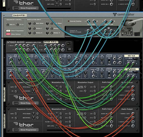
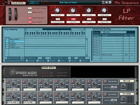
The back of the rack with the Bypass setup
The front of the rack with the Bypass setup shown on Button 4

Keep in mind there are some things that just can’t be stopped on a dime. For instance, changing the delay time or automating changes to the delay time will result in a very distinct sound, almost like a pitch shifting. You just can’t get around this. That’s the nature of audio. So while bypassing most things works without any side effects, other things can still be noticeable. The idea, however, is to minimize the unwanted audio problems as much as you can.


I hope you found these tips useful. I’ll keep posting more as time permits. In the meantime, feel free to share your thoughts or your own tips here by posting a comment. Happy Reasoning!

19 – Spatial-based FX

In a previous tutorial I spoke about how you can create frequency-based FX and divide your FX, sending different delays or phasers or any combination of FX to different frequencies in your mix. This time we’re going to send those same FX to different locations in your mix: Front, Back, Left and Right. This way, we’ll create different FX for 4 different corners of your mix.

In a previous tutorial I spoke about how you can create frequency-based FX and divide your FX, sending different delays or phasers or any combination of FX to different frequencies in your mix. This time we’re going to send those same FX to different locations in your mix: Front, Back, Left and Right. This way, we’ll create different FX for 4 different corners of your mix.

The tutorial files can be downloaded here: 4-corner-spatial-fx This zip file contains 2 Combinators: 4-corner delay FX and 4-corner phaser FX.

Starting of creating the Front and Back sections

First, the video:


  1. First, we’ll start in Reason, and start by opening a new document with all the usual suspects. Create a main mixer, and a sound source (an initialized Thor would do just fine).
  2. Next, create a Combinator under the sound source. Inside the Combinator, hold down shift and create a Unison device (UN-16), Audio Merger/Splitter, 6:2 Line Mixer, Stereo Imager, RV7000, and for our FX device, let’s create a Phaser (PH-90).
  3. Now holding shift down, select the Stereo Imager, RV7000, and PH-90 Phaser, then right click and select “Duplicate Devices and Tracks.”
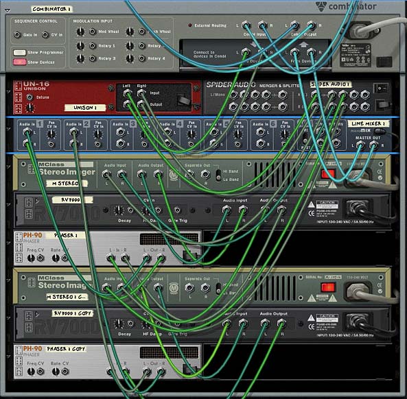
  4. Routing time (note that all the audio routings we’re going to create here are in Stereo pairs): Flip the rack around, and move the Thor Audio outputs into the Combinator Audio inputs. Send the Combinator outputs to Channel 1 on the main mixer. Send the Combinator To Devices outputs into the Unison inputs. Then send the Unison outputs to the Audio Splitter inputs. Send 1 split into the first Stereo Imager’s inputs (we’ll call this the Front Imager), and the second split into the second Stereo Imager’s inputs (we’ll call this the Back Imager).
  5. Continuing with our routing, send the Imager outputs to the RV7000 Inputs (do this for both front and back imagers). Then send the RV7000 outputs to the Phaser inputs (both front and back). Then send the front and back Phaser outputs to Channels 1 and 3 on the 6:2 line mixer. Finally, send the Mixer’s master output to the “From Devices” inputs on the Combinator.

    The Routings on the back of the rack. Looks complicated, but it's really pretty straightforward.
    The Routings on the back of the rack. Looks complicated, but it's really pretty straightforward.
  6. Flip the rack around to the front. Now it’s time to set up some parameters. On the Front Imager, send both the Lo and Hi bands fully Mono (fully left). On the Back Stereo Imager, send both the Lo and Hi bands fully Wide (fully right).
  7. Open up the Remote Programmer on both the front and back RV7000 Reverbs. The Hall algorithms are the default and these are fine for now. On the front Reverb, reduce the size fully (to 13.2 m) and reduce the Global decay to around 50. Increase the HF Dampening to around 84. On the back Reverb increase the size fully (to 39.6 m) and increase the decay to around 98. Also leave the default HF Dampening at around 28. Finally, decrease the Dry/Wet knob on both reverbs to around 30-40 or thereabouts.
  8. Open up the Combinator’s Programmer, select the 6:2 Line Mixer and enter these settings:

Rotary 1 > Channel 1 Level: 0/85

Rotary 3 > Channel 3 Level: 0/85

Now, the First Rotary controls the Front Mix, and the third Rotary controls the back mix. If you play your sound source through this FX Combinator, you’ll hear the front and back sounds by adjusting the Rotaries. But what makes things more interesting is if you apply different settings to your two Phaser devices. Even some subtle changes to the Frequency and Width parameters can provide a much more rich soundscape which makes even Thor’s initialized patch sound pretty interesting.

You can also leave things as they are, or you can move on and create two more spatial corners in our mix by adding both Left and Right panning. In this way, you create a 4-Corner FX split for Front Left, Front Right, Back Left, and Back Right.

Moving from side to side

Now, for the second part in the Video Series:

So let’s continue on our journey and create a split for left and right.

  1. First thing we’ll have to do is hold the shift key down and create two other phasers; one next to the front phaser and another next to the back phaser. Then select the front RV7000 and holding shift down, create a Spider Audio Merger/Splitter. Do the same for the back by holding down the back RV7000 and creating another Spider Audio Merger/Splitter.
  2. Flip to the back of the rack and let’s set up some new routings. Move the cables from the inputs on both Phasers and move these cables to their respective Spider Splitters (in the main Split). Then send one split to the Front Phaser 1 (let’s call this left) and send another split to the Front Phaser 2 (let’s call this right). Then send the outputs from the two new phasers to Channel 3 and 4 respectively.
  3. Flip to the front of the rack and on the 6:2 Line Mixer set the panning for Channels 1 and 3 to about -22 (left) and Channels 2 and 4 to +22 (right). How far left or right you set the panning is really a matter of taste. With this all set up, the 6:2 Line Mixer will be set up as follows:

    Channel 1: Front Left Phaser

    Channel 2: Front Right Phaser

    Channel 3: Back Left Phaser

    Channel 4: Back Right Phaser

  4. Open up the Combinator Programmer, and assign the 6:2 Line Mixer Channel 2 and Channel 4 to Rotary 2 and 4 respectively as follows:

    Rotary 2 > Channel 2 Level: 0/85

    Rotary 4 > Channel 4 Level: 0/85

  5. Now you can provide labels for all 4 rotaries as follows:

    Rotary 1: Front Left

    Rotary 2: Front Right

    Rotary 3: Back Left

    Rotary 4: Back Right

And there you have it. A 4-corner mix with different FX for each corner. You don’t have to restrict yourself to Phasers. With some ingenuity you can assign any FX to any location, or any combination of FX to any of these 4 locations, and all of those with different parameters too. The only thing left is to adjust the Phasers to have different settings as you see fit.

Here’s a video showing you some of the things you can do to modulate the Phasers:

A few other notes:

  • The reason we set up a Unison device in front of the mix is because this ensures that the signal sent into both the imagers is in Stereo. This is needed for the Stereo Imager to function as it should. It won’t work with a Mono signal. It means that even if you use a Subtractor, for example (which is mono), it can still be sent into the Imagers and the Imagers can work their magic.
  • Using the Width / Mono setting on the Imager bands helps to create the illusion of front and back audio locations. Used in conjunction with the Reverbs, you can create some sophisticated positioning not only with your FX, but also audio of any kind. When you move towards Mono, the sound appears to come from the front of the mix. By widening the bands, the sound becomes more spread out and appears to come from the back.
  • Just as with the Imagers, changing the space size and decays on the Reverbs helps the illusion along. Smaller sizes and shorter decays means a tighter reverb space which appears as though the sound is closer. For the back Reverb, the opposite is in effect. By creating a wider space with a longer tail reverb, you end up with a sound that is pressed further back. Keeping the same algorithm type still binds the two reverb spaces together. However, there’s nothing preventing you from trying to use different algorithms altogether (for example, a Small Space reverb for the front and an Arena reverb for the back).
  • Ever look at those Escher drawings where the staircases keep looping back into themselves? They are impossible pictures. Well, the same can be achieved with sound. You can create some really weird effects by creating an impossible space. Try switching the Reverbs around but keeping the Imagers as they are. The Imagers will tell your ears that the sound should be coming from the front and back, but the reverbs will be telling you the reverse. It can be a disturbing effect. But in the virtual world, you can create these “Impossible” sounds easily. Try that one out.

As always I’d love to hear what you think? Show some love and drop me some feedback or any questions you might have. Until next time, good luck in all your musical endeavors.

12 – Crossfading Mals & Filters

Since Ed’s Thor Shaper article, I’ve been thinking about how to use this information in real-world examples. One idea is to crossfade the Grain Samples in the Malstrom and another idea is to crossfade all 4 Thor filters to affect one sound source. Lots of fun!

Since Ed’s Thor Shaper article, I’ve been thinking about how to use this information in real-world examples. One thought came from a post I saw on the Props forum. Basically, the issue was that you can’t assign the Malstrom Grains to a Combinator Rotary to effectively switch between the 80+ Grain Samples. It’s pretty easy to assign and switch between Modulator waveforms using a Rotary, but not the actual samples in the Malstrom. So this got me thinking of how you could go about switching between these Samples. And truth be told, there’s probably some really obscure way to do it which uses Thor and some heavy CV connections. But here is something that might just inspire you and be the next best thing.

You can download the project zip file here: crossfading-malstroms-and-filters. This file contains 2 rns files with the Combinator setups explained below. One is a 16-Malstrom crossfader, and the other is a 4-way Thor filter crossfader. I would recommend you download them and open them up as you read. It will make things a little easier that way.

Crossfading 16 Malstrom Grain Samples

In this setup, I’m using 16 Malstrom devices and each device is sent to a Mixer Channel in two 14:2 Mixers. The CV from the various Thors are sent to the Mixer Levels, where the level trim knobs are pushed all the way right, and the Mixer channel Levels are set to zero. If you haven’t already seen Ed’s interesting and enlightening tutorial on the subject, you should read it here: Ed’s Thor Shaper Tutorial. It goes through using the Sine Wave Shaper in Thor to create a 4-way Crossfader. In this way, you can cross-fade between 4 different Malstroms. Each Malstrom’s Oscillator A is set to a different Sample.

Since you have 4 Rotaries, each Rotary is set to 4 Malstrom devices. Giving you a total of 16 different Oscillators. Also, since one or more oscillators will be playing at any one given time, I’ve set up each button on the Combinator to mute the specific series of Oscillators. Button/Rotary 1 affects the first group of 4 (Malstroms 1-4), Button/Rotary 2 affects the second group of 4 (Malstroms 5-8), and so on. Only 10 Malstroms should be applied to a single Mixer because you can only map 10 parameters from any one device to the Combinator, and you need all 10 channel mutes mapped to the various Combinator buttons.

To take this a step further, you could create 6 Combinators, which together would contain the full 82 Oscillator Samples used by the Malstrom. Then you could crossfade between any oscillator you like. The sweet spots for each of the rotaries are as follows:

0 = Oscillator 1 Full Level

42 = Oscillator 2 Full Level

85 = Oscillator 3 Full Level

127 = Oscillator 4 Full Level

Any integer between those values will provide a crossfade between the two Oscillators on either side of the value. This can be seen as a downside or an upside. If you want a pure switch between Oscillator 2 and 4 for example, you can automate the Rotary to go straight from 40 to 85 in your sequencer using a Rotary automation lane. In this sense, you can use the Rotary as a 4-way button switcher between each Oscillator.

On the downside, you couldn’t effectively crossfade between Oscillator 2 and Oscillator 6 (on Rotary 2) the way the current Combinator is set up. But if you Reorganize the way the buttons mute, you could effectively do this. I’m open to anyone who has any other suggestions on how this could be achieved. Another downside is that since a different Malstrom is used for each Oscillator, you’ll have to tweak the settings on each Malstrom to get exactly the sound you want. If you want to keep everything consistent between all Malstroms, you’ll have to do it through automation (the easiest way I think). Simply automate one parameter on the first Malstrom in the sequencer, and copy that automation clip into every other Malstrom’s automation lane. It’s a bit of a pain, but it will keep all Malstroms in line, if that’s what you want.

On the upside, since there are 16 different Malstroms, you can fine tune the sound of each of them separately. If you have all the mutes off, you can effectively crossfade between 4-8 Malstrom sounds/devices at once just by shifting the Rotaries around. This adds some very interesting Sound Layering potential.

As it stands, the first 16 Oscillators from the Malstrom are applied to the 4 Rotaries on the Combinator. As I said, you could build up a stack of 6 Combinators to include all the Malstrom Oscillators. In this way you can build up various sounds and switch between the various Oscillators. Does this help anyone out?

Crossfading all 4 Thor Filters, and then some. . .

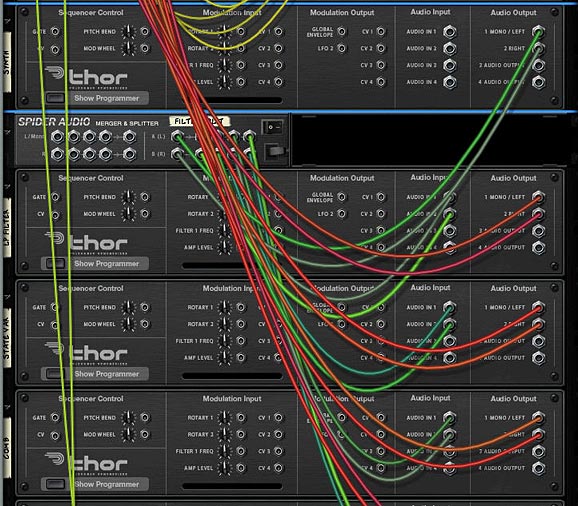
Next, let’s take a look at how we can crossfade all of Thor’s filters to affect one synth sound. In this case, it’s fairly simple to set up. First, create a Combinator, and set up Ed’s 3 Sine Shaper Thor’s to handle the CV like the previous example (along with a 14:2 Mixer). Then create a Thor and load up a synth sound. Start off with something simple so that you can really hear the different filters affecting the sound. Then create a Spider Audio CV Merger / Splitter, and send the synth’s Left and Right Audio Outputs to the splitter’s inputs. Create 4 Thors underneath the splitter and send each of the 4 splits to these respective Thor’s Audio Inputs 1 and 2. Finally, send the 4 Thor’s Left and Right Audio Outputs to the first four 14:2 Mixer channels.

The setup with The Sine Shaper CV and Audio outputs from Thor into the Mixer
The Thor Synth Audio being split and sent through the 4 Thor Filters

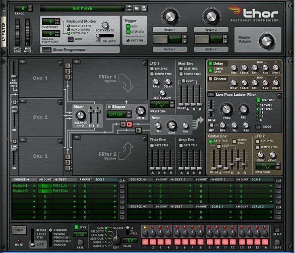
On the front of the Rack, add a Low Pass Ladder Filter in the first Thor’s Filter 3 Slot. The settings for this filter are shown in the image below. In addition, add the following into the Modulation Bus Routing System (MBRS):

Audio In1: 100 > Filt3 L.In

Audio In2: 100 > Filt3 R.In

The Low Pass Ladder Thor Filter settings on the front Panel

Enter the same settings in the other 3 Thors, but with different filters, so you have the State Variable filter in Thor 2, Comb filter in Thor 3, and Formant filter in Thor 4. While you’re at it, play around with the Global ADSR envelope so that it sounds to your liking for the 4 different filters. It’s ok if these settings are different for each filter. This will just make your sound more interesting. One thing I kept the same across all 4 Thor Filters is the FX section (Delay and Chorus). This way, when the filters are transitioned, the FX remain similar across the board.

Now let’s turn to our Combinator section and do some serious routings in the Mod Matrix. Here’s the settings you will need for each of the Thor Filters (they are the same for all 4, but must be applied to all 4):

Rotary 1 is reserved for the Filter Crossfade, so I’m not going to go over it here. You can see it in the Project File rns.

Rotary 2 > Filter 3 Freq: 0 / 127

Rotary 3 > Filter 3 Res: 0 / 127

Rotary 4 > Filter 3 Global Env Amount: 0 / 127

Button 1 > Delay On: 0 / 1

Button 2 > Delay Sync: 0 / 1

Button 3 > Chorus On: 0 / 1

Button 4 > Filter 3 Global Env Invert: 0 / 1

Mod.W > Filter 3 Drive: 50 / 127

The Combinator Mod Bus Routing settings for each of the Filters

Now, what’s happening is that the Mod Wheel controls the drive amount on each of the Filters, While Rotary 1 cross-fades all the filters. This is the main Rotary, and it has the same sweet spots as the previous Malstrom patch. Rotary 2 and 3 control the Frequency and Resonance of the filters, and Rotary 4 adjusts the Envelope of the filter. Button 4 inverts this envelope. The remaining buttons are left for the Delay, Delay Sync and Chorus. Since all the parameters are the same for all the filters, they all shift together. This can be a positive or a negative. You can’t individually set the filters, but at least they sound pretty good when transitioned. Depending on your ADSR settings for the Global Filter, the Envelope Rotary and Envelope Inversion Button may be different for each filter. But as I said before, this can add some nice variety to the sound.

Use this Combinator as a template for your own sounds. All you have to do is add your own patch into the Thor “Synth” or change the Thor “Synth” to any other Synth or Sampler device if you like. Then you’re in filter crossfading heaven.

A huge thanks to Ed for being the inspiration for these patches. Please let me know what you think and if you can think of any other applications that this crossfading technique can have, by all means share it with us. Until next time, have fun with these.

4 – Map Reason Songs to Record

Learn how to transfer all settings from one channel in the Reason Mixer to one channel in the Record Main Mixer. With this technique you can properly tranfer any song with any mixer settings from Reason to Record.

As a beta tester, when I got Record I was super excited. I promptly downloaded and installed, and went to open it up. I was salivating by the time all three record windows were opened stacked in front of me on my screen. The “AHHHHH” moment. A halo emanated around my computer. Come on, you know what I mean. I first saw the double rack and was amazed. Then I looked at the main mixer and my jaw hit the ground. Beautiful! A work of art. now I can finally work on making my tracks truly sing.

Then I opened a Reason song. And everything that I had hoped and dreamed got shattered in one swift moment. What? My mixer with 9 tracks and automation applied to the sends, EQ settings, panning, levels got reduced to a measly single track attached to the new main mixer in Record. All my earlier praise now turned to dismay.

I’m sure most of you know exactly what I mean. You’ve been there. You’ve gone through the same agony. So what do you do now? Curl up in a ball? Send Record back to the Props? Well, you could do that. Or you can read this tutorial and learn how to properly transfer all your settings from the 14:2 mixer in Reason into the SSL Main Mixer in Record. It’s not that hard, as you’ll see. But it is a little time consuming, depending how many tracks you have. And I’m not going to undertake doing an entire song mix. What I’ll do is show you how to transfer all settings from one channel in the Reason Mixer into one channel in the Record Main Mixer. Once you have that down, you can do any number of channels, no matter how complicated the song. So let’s get busy.

Before starting, I’ve put together a zip package with the project files. It contains the Reason song with a single channel and the Record version of the same song once it was converted: Download the Project Files.

It should be noted here that if you have not yet done any serious mixing in your main reason mixer, and don’t have any automation set up for any mixer parameters AND don’t have any CV setup for the Pans/Levels on the back of the mixer, then you can safely open the Reason song in Record and delete your main mixer. Then you can select all the (now disconnected) devices, right-click, and choose “Auto-route Device.” This will create Mix Channels for all the devices. Depending on how creative your connections were to begin with, you may find a few devices that require some custom routing after you do this. [thanks to Mattpiper from the Props forum for this excellent tip]

However, if you already have your mix set up with a lot of automation applied to the Reason main mixer device, then read onward, because this article is for you!

  1. First thing, open the Reason song, mixer and all, in Record.
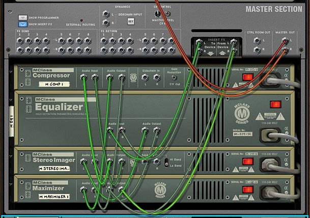
  2. Next, you’re going to have to move any mastering Combinator or devices into the Master Section in Record. Let’s say we have a “Dance” Combinator inserted between the Reason Mixer and the Hardware Interface. Select all the devices in the Dance Combi and move it into the Master Section. Flip the rack around, and move the “From Devices” and “To Devices” cables from the Dance Combi to the same ins/outs of the Master Section. Then delete the audio ins/outs from the dance Combi, and delete the Dance Combi altogether. You don’t need it anymore.
  3. Adding the mastering Combi into the Master Section
    Adding the mastering Combi into the Master Section
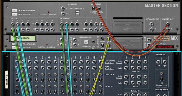
  4. Now let’s assume you have a Matrix set up to control the Panning of the channel, and another Matrix set up to control the Level of the channel. You’ll have to flip to the back of the rack, and move the CV inputs from the Reason Mixer to the CV inputs of the Mix channel. Then adjust the pots to the same settings they were at in the Reason Mixer. Level and Pan is done. Note that if you have several channels set up in your song, you’ll have to create the same number of Mix devices in Record.
  5. Pan / Level CV rerouted through the Mix Device
    Pan / Level CV rerouted to the Mix Device
  6. Next, let’s move the Aux Sends/Returns from the Reason Mixer to the Master Section’s Sends/Returns in Record. This is pretty straightforward. Plus in Record you can now set up 8 Aux sends if you want, which is more than enough power. But in the example I’ve provided there was a Reverb and a Delay set up. So we’ll move those over now.
  7. Send / Return cable rerouting to the Master Section
    Send / Return cable rerouting to the Master Section
  8. Our last cable job is to move the Lead Audio Cables from the first channel in the Reason Mixer over to the Main L/R input on the Mix Device. You can now flip the rack around. You’re done with the cabling.
  9. Cabling the Main Audio outs from the Lead track
    Cabling the Main Audio outs from the Lead track to the Input on the Mix Device
  10. Now let’s move to the Record mixer. Press F5 and F6 at the same time to show both the rack and the main mixer in record. If your channels have any settings that ARE NOT automated, but are static for the entire duration of the song (and are different from their default setting), then you can adjust those settings on the main mixer channels in Record. For example, if a channel is set to a level of 90 in the main Reason mixer, and stays at 90 through the duration of the entire song, then you can change the dB level on the Main Record Mixer’s channel to -2.8 dB and leave it there. If the Level stays at 100 for the duration of the entire song in Reason, then you won’t need to change a thing in Record, because the level is already set to 0.0 dB. Make sense so far?
  11. At this point, you’ve probably realized that the new Mixer in Record use decibel values, not midi values. This is a good change, however, it makes it a little difficult to translate levels and send values from the old mixer. So I put together this little chart in PDF format that you can download to see the values. You may not get to use those exact values shown in the chart due to the jumps between values in the Record Mixer, but you can get pretty close. Thanks to Selig on the Props forum for the chart values. Download the Midi to dB Conversion Chart. Note that the chart is also included in the Project Files zip above.

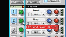
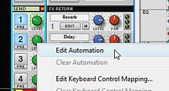
  12. Next, turn the sends 1 and 2 on in the Main Mixer’s Send section in Record. Since the example file has automation set up for these sends, right-click and select Automate. Do this for both sends. However, don’t move to the sequencer just yet. Instead, Look at the other elements on the channel that are automated, and do the same for those as well. So in our example, the solo and level parameters are automated, so right-click and select “Edit Automation” for those two parameters as well.
  13. Turning on and adjusting the Send settings
    Turning on and adjusting the Send settings
    Selecting "Edit Automation" for all parameters which were automated in the Reason Mixer
    Selecting "Edit Automation" for all parameters which were automated in the Reason Mixer
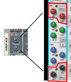
  14. One last thing in the Mixer. If you’ve adjusted the Reason Mixer’s EQ settings for Bass and Treble, you’ll have to map that over to the Record mixer as well. The best way to do this is to adjust the HF (High Frequency) and LF (Low Frequency) settings in the EQ section of Record’s main mixer. This is a shelving EQ which controls your bass and treble. Note that it gives you more control over the Bass/Treble settings that you’d find on the 14:2 Mixer in Reason, because it allows you to dial in the proper frequency range to affect. So you’ll have to use your ears for this one. For more on the EQ settings found in the new Record Mixer, you should read Ernie Rideout’s great article: Tools for Mixing: EQ (Parts 1 and 2).
  15. Converting the Treble and Bass EQ settings
    Converting the Treble and Bass EQ settings
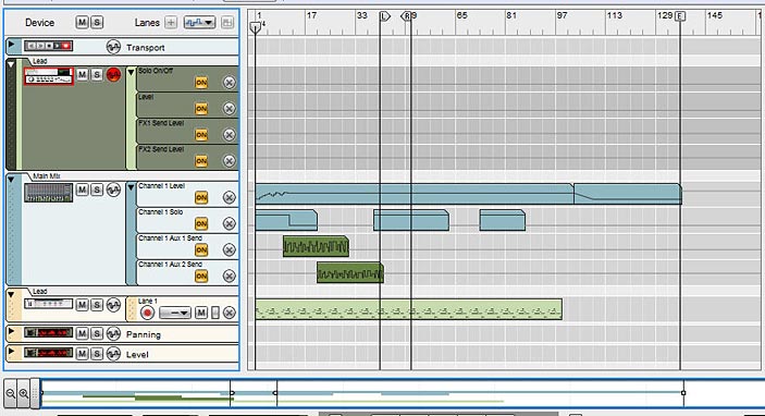
  16. Finally, we move to the sequencer. Press F7 on your keyboard to open the Sequencer. Notice that you have the Mixer with all the parameter automation, but since you selected “Edit Automation” for all those same parameters in Record’s mixer, you have all those lanes set up under the Mix Device. Now it’s just a matter of moving the clips from the Mixer into the proper lanes in the Mix Device. To make things easier (if your song is very long), expand the view by dragging the view window along the bottom of the sequencer all the way to the right, or click the “Zoom Out” magnifying glass at the bottom-left in the horizontal scroll view.
  17. Zooming out to see the whole track in view along the timeline
    Zooming out to see the whole track in view along the timeline
  18. When you move the automation over, some lanes may show “Alien Clips.” To convert the lanes to proper automation, right-click and select “Adjust Alien Clips to Lane.”
  19. Adjusting Alien Clips to Lane
    Adjusting Alien Clips to Lane
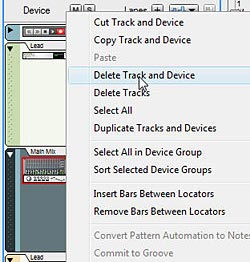
  20. And last but not least, right-click on the Mixer device in the sequencer and select “Delete Track and Device.” You won’t need it anymore. You’ve now converted your Reason song into Record and are free to mix and master your song using the SSL Mixer in Record. The sound should be pretty darn close to the original mix in Reason.
  21. The Final step: Deleting the Mixer
    The Final step: Deleting the Mixer

Be sure to save your song as a .record file. You’ll still have the original Reason song saved away which you can open as a reference, as opening Reason songs in Record does not overwrite your Reason song. It leaves it as is. The really nice thing about the Record mixer is that it gives you a wide array of other options which cannot be found on the Reason mixer, such as High and Low Pass filters, Compression, and a Main Compressor you can apply to the overall mix. More Sends, and handling of rotary and button controls for your devices makes this mixer a huge and powerful addition to your Reason software. So go forth and convert. It takes some time, but the more you do it the better you’ll get at it.

What are your experiences with song conversion from Reason to Record? Did you find this helpful? Is there anything I’ve missed? Please comment and let me know.