
This article will introduce you to the Etch Red RE from FXpansion. This Rack Extension is a powerful dual multi-mode filter that can be set up in series or parallel. It also comes with a comprehensive built-in and external modulation scheme that is unlike any other in the stock Reason program. Aside from filtering, it is capable of several tricks such as gating, stereo widening, compression, distortion, LFO wobbling, Tremolo, and Vibrato effects. To top it all off, it comes with the ability to Frequency Modulate the filters (either internally via the 2 built-in LFOs, or externally using an incoming audio source). A lot of power for a very affordable Reason device. So let’s take a walk-through and learn a little more about it.
Before I get into the nuts and bolts of the device, let me first point you to the PDF User Manual that you can download. This comes straight from the FXpansion site, and it’s a good idea that you have a read before jumping in. There’s a few pitfalls that you want to avoid when working with this Rack Extension, and while it’s a very nicely designed device, there’s still some areas that might cause you to scratch your head.
Next, let me point out the main features of this Rack Extension in a simple video:
It’s all about Source > Destination = Modulation.
The heart of Etch Red is all the wonderful red knobs scattered throughout the upper (Filters) and lower (Sources) section of the device. These knobs allow you to modulate their associated parameters with one or more of the 10 Sources (selected in the Middle section of the device). Indeed you can modulate one parameter with all 10 sources if you like. Where I can see a lot of people getting tripped up is when you start trying to figure out how to modulate one destination with these Multiple Sources. So here’s a step-by-step tutorial to help you get your feet wet with this concept:
- Create a Subtractor, Thor, NNXT, or any other sound-generating device in Reason, or else create a new Audio Track and place some audio on this track. My recommendation is to go for a nice Pad sound to start yourself off. Load up a Pad patch from the Factory Sound Bank if you are stumped for creativity.
- Create an Etch Red device underneath so that it is auto-routed to the sound device (hint: Etch Red is found in the Creative FX menu if you right-click under the sound device). If all goes well, the sound device’s Left and Right audio goes into the Etch Red device, and then back out to the Mix Channel or Audio Track.
- Set the LFO1 Rate to be 1/2 bars and LFO2 Rate to be 1/16 bars. Both are Synced by default. Also adjust their Gain settings to both be set to around 66%. This will remove the harshness of the LFO curve. It’s like a depth or volume setting for the modulation source.
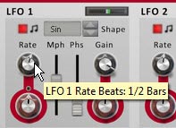
Setting the LFO1 Rate to 1/2 Bars in the Source (bottom) section of the device 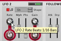
Setting the LFO2 Rate to 1/16 Bars in the Source (bottom) section of the device - Select a Source from the middle “Modulation Source Selection” section of the device. By default, the LFO1 is selected as a source. You can see this because the little LED within the square icon is yellow. You can also select a source using the drop-down list to the right of all 10 sources. For this example, we’ll use both LFO1 and LFO2 as a source to modulate both Filter Frequencies. Keep LFO1 selected for now. Click the tiny square red LED light just to the bottom right of the LFO1 selector. Turning it off switches the polarity of LFO1 from Unipolar to Bipolar. Leave LFO2 set to Unipolar, which is the default.

The Modulation Source Selection (middle) area of Etch Red. Note that the LFO1 selector is yellow. You can select a source by pressing these square icons, or by clicking from the drop-down list (both are shown here with a black square border). 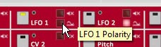
Setting the Polarity of LFO1 to Unipolar by turning the LED off. This ensures the LFO travels both negatively and positively to affect the destination parameter. - Next, switch the Filter 1 Mode to a 4-Pole High Pass Filter (4H) and the Frequency to 6 Hz (fully left). For Filter 2, leave it set to the Low Pass Filter (default), and set the Frequency to around 350 Hz or so. Also set its Resonance (Rez Rotary) to roughly 25%. Note: The Black rotaries change the parameters. The Rotaries encased in Red circles are used to modulate these parameters. So Black changes the parameters outright, while red is used to modulate them negatively (left) or positively (right).
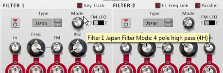
Setting Filter 1 Mode to a 4-Pole High Pass Filter. 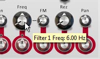
Setting the Filter 1 Frequency to 6 Hz. 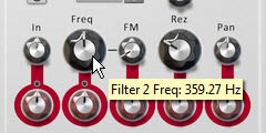
Setting the Filter 2 Frequency to around 350 Hz and the Resolution (Rez) to about 25%. - Now we’re set to actually use the sources to modulate the Filters. Using the Red Modulation Rotaries, set the rotaries beneath both filter Frequency parameters to positive 28%. You’ll start to hear the sway of LFO1 affecting the sound as you play the sound device.
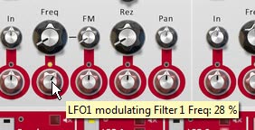
Adjusting the Modulation of the Filter 1 Frequency. - Select LFO2 by clicking on the square icon in the middle section of the device or using the drop-down at the far right of the 10 Mod Sources. When you switch over to a new Modulation Source, you’ll notice that both filter frequencies’ Modulation Rotaries snap back to their original values (dead center). You’ll also notice that the small LED circle just above these rotaries turn red. This LEDs indicate that there is another source modulating this parameter. Finally, the previous source’s square selector changes from yellow to red (LFO1 in this case). Switch back to LFO1, and these LEDs turn yellow. Switch back to LFO2, the parameters go back to their default and the LEDs turn Red. Yellow = whatever is currently selected in Etch Red. Red = another value is being used to modulate this parameter.
Note: The one thing that I dislike about working with Etch Red is the fact that when you start creating complex modulations and have several sources modulating a certain Destination, there’s no immediate way to see which sources are modulating the parameter and by how much. You have to click on each source to see how it is affecting all its associated destinations. On the flipside, this does make experimenting with complex modulation assignments quick and you can easily get lost in experimentation. So that’s a plus!
- With LFO2 as the selected source, change the Modulation Rotary underneath Filter 2 to a positive 50%. You now have the Frequency for Filter 2 being modulated by both LFO1 and LFO2. That’s pretty much all there is to it.
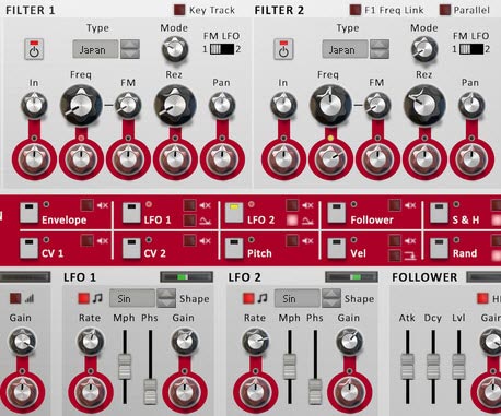
The Final Etch Red Filter, Mod Source Selection, and Sources sections. Note how LFO2 and the LED just above the Modulation rotary for the Filter 2 Frequency are yellow, indicating LFO 2 is the currently selected source, and Filter 2 Frequency is being modulated by LFO2. On the other hand the LED above the Modulation Rotary for the Filter 1 Frequency parameter is red, indicating it is being modulated by another source (in this case, LFO1).
Note: Of course, you can also modulate a Source’s Rate or Gain settings (at least for the sources listed in the top row of the Modulation Source Selection area) by adjusting the red Modulation Rotaries underneath these parameters (in the bottom section of the device). This can also open up some very complex modulations. You can even use LFO1 to modulate its own Rate and Gain. How trippy.
Getting a little more Advanced
So now that we have a grasp on how Etch Red works, I thought I would delve a little deeper into things by using the Envelope source. In order to get the envelope working, you need to send a Gate input signal into the back of the device. And what better way to trigger the envelope than with a Rex loop’s Gate output. So here’s a little video that shows a few techniques along those lines:
Everyone Loves a Dubstep Bass, right (or am I being sarcastic)?
Here’s a great video put together by FXpansion themselves that goes over the process of creating a Dubstep Bass using their device. It’s a little more advanced, but it’s a great way to showcase how some of the CV modulations can be used on the back of their device. And the sound is just cool, so I had to include it here:
More Tips and Tricks
Here are a few other handy tricks you can try out using Etch Red.
- Fun with Distortion: Unsync LFO 1 and select it as a mod source. Set its rate to somewhere around 100-600 Hz. Set the output level to -14 dB. Turn up the Drive Mod Rotary slowly. adjust the LFO 1 Rate, Mph, and Drive Types until you find something you like. Great for basses.
- Tremolo: Select the LFO 1 as a mod source and click the Polarity LED to make it bipolar. Adjust the Level Mod rotary set to a small amount in either direction for Tremolo.effects.
- More Shapes: Create a Malstrom and from the back send Mod A into Etch Red’s CV 1 input. You can now use Malstrom’s 31 waves as a source to affect any Etch Red Modulation.
- Dual Filter Gates: Turn off Drive and Filter 2. Set LFO 1 & 2 with “Square” shapes. Ensure the rates are synced, but different for each (ex.: 1/4 & 1/16). Keep the Gain full. Select LFO 1 as a source, and Set Filter 1 to Low Pass (Japan, SVF, or Fatty). Set the Frequency to 6 Hz (full left). Then turn the Frequency Mod Rotary to 100% (full right). Now select LFO 2 as a Source and use it to modulate the same Filter 1 Frequency in the same way (Mod Rotary to 100% – full right). Adjust the depth of both LFOs by adjusting their Gain values.
- Auto-Panner: Set LFO 1 to Bipolar. Then use LFO 1 as a source adjusting the Pan Mod Rotary for Filter 1. Adjust the LFO 1 settings to taste.
- FM Audio Fun: Try sending audio from a Loop or a synth into the Filter 1 and/or 2 FM inputs. Then on the front, turn up the FM Rotaries, and adjust the Filter Freq & Res to taste. Noise and Saw Oscillators are great audio inputs too (though you may need to raise their volume). For further manipulation, assign an LFO to modulate the FM amount.
- Envelopes: To use the Etch Red Envelope, you need to send a CV signal into the Gate CV input on the back. Try sending a matrix Gate CV into the Gate CV input. Now put together a gate pattern in the matrix. Alternately, you can send a Curve CV from the Matrix. Now you can use the Envelope modulation source to modulate any Etch Red Mod Parameters.
- Key Tracking your Filters: To use the Etch Red “Key Track” feature, create a Sequencer Track for Etch Red. Then copy MIDI data from another Track (some monophonic data works best). Then reduce the Filter Frequency. When you play back the Sequencer, the Filter will follow the MIDI track, and will in essence be following the musical track from which you stole the MIDI data. Or you can just play along on your keyboard to track the Filters.
- Internal Pitching: Try sending the LFO 1 CV output to the Pitch CV input on the back of Etch Red. Then turn on Key Track on the front, and set up your Filter. Choose a Fatty LP filter for a nice bassy sound. Set Freq to about 185 Hz, Rez to 70%, and set LFO 1 Rate to 34 Hz, Free-running, and Mph to about 77%. Oh yeah, some nice Bass Wobbling.
Hope you enjoy Etch Red as much as I do. It’s capable of quite a lot. If you have any other ideas, tips and tricks, please share them with the class.


