19 – Spatial-based FX

In a previous tutorial I spoke about how you can create frequency-based FX and divide your FX, sending different delays or phasers or any combination of FX to different frequencies in your mix. This time we’re going to send those same FX to different locations in your mix: Front, Back, Left and Right. This way, we’ll create different FX for 4 different corners of your mix.

In a previous tutorial I spoke about how you can create frequency-based FX and divide your FX, sending different delays or phasers or any combination of FX to different frequencies in your mix. This time we’re going to send those same FX to different locations in your mix: Front, Back, Left and Right. This way, we’ll create different FX for 4 different corners of your mix.

The tutorial files can be downloaded here: 4-corner-spatial-fx This zip file contains 2 Combinators: 4-corner delay FX and 4-corner phaser FX.

Starting of creating the Front and Back sections

First, the video:


  1. First, we’ll start in Reason, and start by opening a new document with all the usual suspects. Create a main mixer, and a sound source (an initialized Thor would do just fine).
  2. Next, create a Combinator under the sound source. Inside the Combinator, hold down shift and create a Unison device (UN-16), Audio Merger/Splitter, 6:2 Line Mixer, Stereo Imager, RV7000, and for our FX device, let’s create a Phaser (PH-90).
  3. Now holding shift down, select the Stereo Imager, RV7000, and PH-90 Phaser, then right click and select “Duplicate Devices and Tracks.”
  4. Routing time (note that all the audio routings we’re going to create here are in Stereo pairs): Flip the rack around, and move the Thor Audio outputs into the Combinator Audio inputs. Send the Combinator outputs to Channel 1 on the main mixer. Send the Combinator To Devices outputs into the Unison inputs. Then send the Unison outputs to the Audio Splitter inputs. Send 1 split into the first Stereo Imager’s inputs (we’ll call this the Front Imager), and the second split into the second Stereo Imager’s inputs (we’ll call this the Back Imager).
  5. Continuing with our routing, send the Imager outputs to the RV7000 Inputs (do this for both front and back imagers). Then send the RV7000 outputs to the Phaser inputs (both front and back). Then send the front and back Phaser outputs to Channels 1 and 3 on the 6:2 line mixer. Finally, send the Mixer’s master output to the “From Devices” inputs on the Combinator.
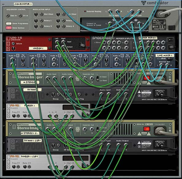
    The Routings on the back of the rack. Looks complicated, but it's really pretty straightforward.
    The Routings on the back of the rack. Looks complicated, but it's really pretty straightforward.
  6. Flip the rack around to the front. Now it’s time to set up some parameters. On the Front Imager, send both the Lo and Hi bands fully Mono (fully left). On the Back Stereo Imager, send both the Lo and Hi bands fully Wide (fully right).
  7. Open up the Remote Programmer on both the front and back RV7000 Reverbs. The Hall algorithms are the default and these are fine for now. On the front Reverb, reduce the size fully (to 13.2 m) and reduce the Global decay to around 50. Increase the HF Dampening to around 84. On the back Reverb increase the size fully (to 39.6 m) and increase the decay to around 98. Also leave the default HF Dampening at around 28. Finally, decrease the Dry/Wet knob on both reverbs to around 30-40 or thereabouts.
  8. Open up the Combinator’s Programmer, select the 6:2 Line Mixer and enter these settings:

Rotary 1 > Channel 1 Level: 0/85

Rotary 3 > Channel 3 Level: 0/85

Now, the First Rotary controls the Front Mix, and the third Rotary controls the back mix. If you play your sound source through this FX Combinator, you’ll hear the front and back sounds by adjusting the Rotaries. But what makes things more interesting is if you apply different settings to your two Phaser devices. Even some subtle changes to the Frequency and Width parameters can provide a much more rich soundscape which makes even Thor’s initialized patch sound pretty interesting.

You can also leave things as they are, or you can move on and create two more spatial corners in our mix by adding both Left and Right panning. In this way, you create a 4-Corner FX split for Front Left, Front Right, Back Left, and Back Right.

Moving from side to side

Now, for the second part in the Video Series:

So let’s continue on our journey and create a split for left and right.

  1. First thing we’ll have to do is hold the shift key down and create two other phasers; one next to the front phaser and another next to the back phaser. Then select the front RV7000 and holding shift down, create a Spider Audio Merger/Splitter. Do the same for the back by holding down the back RV7000 and creating another Spider Audio Merger/Splitter.
  2. Flip to the back of the rack and let’s set up some new routings. Move the cables from the inputs on both Phasers and move these cables to their respective Spider Splitters (in the main Split). Then send one split to the Front Phaser 1 (let’s call this left) and send another split to the Front Phaser 2 (let’s call this right). Then send the outputs from the two new phasers to Channel 3 and 4 respectively.
  3. Flip to the front of the rack and on the 6:2 Line Mixer set the panning for Channels 1 and 3 to about -22 (left) and Channels 2 and 4 to +22 (right). How far left or right you set the panning is really a matter of taste. With this all set up, the 6:2 Line Mixer will be set up as follows:

    Channel 1: Front Left Phaser

    Channel 2: Front Right Phaser

    Channel 3: Back Left Phaser

    Channel 4: Back Right Phaser

  4. Open up the Combinator Programmer, and assign the 6:2 Line Mixer Channel 2 and Channel 4 to Rotary 2 and 4 respectively as follows:

    Rotary 2 > Channel 2 Level: 0/85

    Rotary 4 > Channel 4 Level: 0/85

  5. Now you can provide labels for all 4 rotaries as follows:

    Rotary 1: Front Left

    Rotary 2: Front Right

    Rotary 3: Back Left

    Rotary 4: Back Right

And there you have it. A 4-corner mix with different FX for each corner. You don’t have to restrict yourself to Phasers. With some ingenuity you can assign any FX to any location, or any combination of FX to any of these 4 locations, and all of those with different parameters too. The only thing left is to adjust the Phasers to have different settings as you see fit.

Here’s a video showing you some of the things you can do to modulate the Phasers:

A few other notes:

  • The reason we set up a Unison device in front of the mix is because this ensures that the signal sent into both the imagers is in Stereo. This is needed for the Stereo Imager to function as it should. It won’t work with a Mono signal. It means that even if you use a Subtractor, for example (which is mono), it can still be sent into the Imagers and the Imagers can work their magic.
  • Using the Width / Mono setting on the Imager bands helps to create the illusion of front and back audio locations. Used in conjunction with the Reverbs, you can create some sophisticated positioning not only with your FX, but also audio of any kind. When you move towards Mono, the sound appears to come from the front of the mix. By widening the bands, the sound becomes more spread out and appears to come from the back.
  • Just as with the Imagers, changing the space size and decays on the Reverbs helps the illusion along. Smaller sizes and shorter decays means a tighter reverb space which appears as though the sound is closer. For the back Reverb, the opposite is in effect. By creating a wider space with a longer tail reverb, you end up with a sound that is pressed further back. Keeping the same algorithm type still binds the two reverb spaces together. However, there’s nothing preventing you from trying to use different algorithms altogether (for example, a Small Space reverb for the front and an Arena reverb for the back).
  • Ever look at those Escher drawings where the staircases keep looping back into themselves? They are impossible pictures. Well, the same can be achieved with sound. You can create some really weird effects by creating an impossible space. Try switching the Reverbs around but keeping the Imagers as they are. The Imagers will tell your ears that the sound should be coming from the front and back, but the reverbs will be telling you the reverse. It can be a disturbing effect. But in the virtual world, you can create these “Impossible” sounds easily. Try that one out.

As always I’d love to hear what you think? Show some love and drop me some feedback or any questions you might have. Until next time, good luck in all your musical endeavors.

17 – Auto-Panning Methods

Learn a few different ways to automatically pan your audio back and forth from left to right or right to left in the stereo field using the LFOs of the Reason synth devices or a Matrix pattern device. As you’ll see, these methods are not that difficult to understand or implement.

Here I’m going to go over a few different ways you can automatically pan your audio back and forth in the Stereo field. As you’ll see, the methods are not that difficult to understand or implement. Once you have this process down, you can also go on to do more complicated panning techniques, such as combining waveforms for panning, panning filter frequencies, or panning your EQ to create left to right frequency sweeps. Of course, I’m not going to go into all of these advanced techniques. Rather, I’ll delve into the world of auto-panning slowly to get your mind wrapped around some of the different methods you can use in Reason and Record.

Download the project files here: auto-panning-methods. This is a single .rns file with 4 different Auto-Panning Combinators set up for you. Each one affects the same audio source and then gets sent to their own mixer channels in the 14:2 mixer. Mute/solo the channel you want to hear to listen to the examples. Note that each Combinator in this set uses a different way to pan the signal. Each has their strengths and weaknesses, as you’ll see in the tutorial below.

At it’s heart, panning simply moves your sound from Left to Right or Right to Left in the stereo field. In order for the software to pan your sound, you must set up something that signals the audio to move from one side to the other. Usually, this means assigning an LFO or Mod Envelope to control the pan position of your audio. Since Reason and Record have CV inputs assigned to every channel in their mixers, as well as directly on the Mix and Audio Devices themselves, panning any audio source can be achieved with one simple CV connection. Also note that you can pan a mono signal from one side to the other just as you can pan a stereo signal from one side to the other.

Setting up a simple Pan using the Subtractor LFO1

Here is one of the easiest ways to create your automatic panning using the LFO of a Subtractor device:

  1. Open up your audio source in Record or Reason. This can be any synth device, audio channel, mix channel, etc. The point is that you need an audio source to affect.
  2. Next, create a Combinator. Then inside the Combinator, hold your Shift key down and create a 6:2 line mixer and a Subtractor.
  3. Initialize the Subtractor. This means reducing all the values in the Subtractor to zero (range/polyphony/ADSR envelopes, etc.).
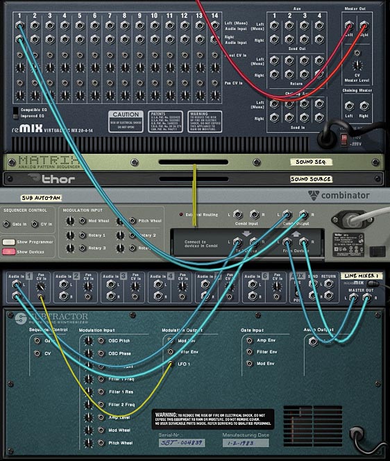
  4. Press the “Tab” key to flip the rack around to the back. Connect the Combinator’s Left and Right “To Devices” to the Mixer’s first channel’s Left and Right inputs. It’s not shown in the image below, but you’ll have to also route the audio source Left and Right output to the Left and Right Combinator input.
  5. Connect the LFO1 CV out from the Subtractor’s Modulation Output section into the Pan CV in on the mixer’s first channel. Then turn the trim knob all the way right. This means that the CV will fully control the panning of the audio source.
The back of the rack showing the Subtractor LFO1 modulating the Pan of the Sound Source.

With this setup, the subtractor’s LFO1 is controlling the audio position in the stereo field. This is a great setup, however, there are two main problems: 1. You have access to a very limited set of LFO waveforms (6 to be exact), and none of those waveforms is a straightforward “sine” wave. And 2. Since the Subtractor is free-running, there’s no way for you to turn off the LFO. It will continually pan from side to side, with the Panning speed based on the Rate in the LFO1 section. I can live with #1, however, #2 is a huge hindrance and is enough for me to say no thanks! Let’s find a better way.

Panning with the Malstrom Curves (a step upward)

Now let’s up the game a little.

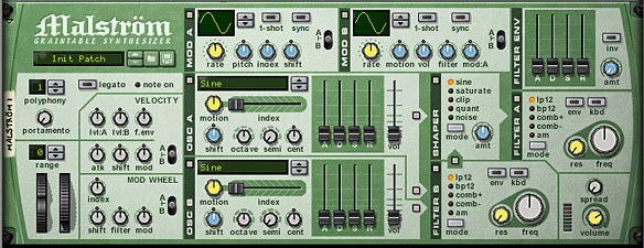
  1. Delete the Subtractor we just created, and instead hold the shift key and create a Malstrom device. Again, initialize the device by moving all the faders to zero and reducing the polyphony to 1 and the pitch range value to zero. Turn everything off except for the “Modulation A Curve” — leave that little light on.

    The fully initialized Malstrom
    The fully initialized Malstrom
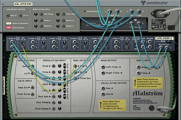
  2. Flip to the back of the rack, and route a CV cable from the Mod A output to the Pan CV in on the line mixer.

    The back of the rack showing how Mod A is controlling the Pan CV in on Mixer Channel 1
    The back of the rack showing how Mod A is controlling the Pan CV in on Mixer Channel 1

Now the Curve from Mod A is controlling the Panning for the sound source. The nice thing about this setup is that you can turn Mod A on or off, which in turn turns the panning on or off (unlike previously in our Subtractor example). Furthermore, there’s another added benefit: you can select from the Malstrom’s 32 different waveforms. Now that’s some serious power.

Panning with Thor (an alternative)

The Malstrom is great if you want to play with a lot of curves to pan your sound source. However, there are a few advantages to using Thor’s LFO2 instead.

For a detailed run-through of how to setup Thor to auto-pan your sound source, have a look at the video below:

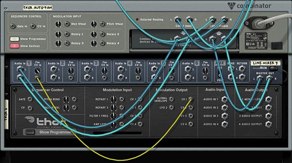
In this situation, you would delete the Malstrom, and initialize a Thor in its place. Send the CV1 Output to the Pan CV in on channel one of the line mixer. Then in Thor’s mod matrix, you use LFO2 as a source and CV1 Out as a destination. Finally, you could set up a button on the Combinator so that when the button was off, Thor’s “Mod Destination Amount” is set to zero (0), and when turned on, it is set to 100. This way, the button acts as a switch to turn the CV on/off. Just have a look in the project files to see how this is set up.

Thor CV1 out going to the Pan CV in on the first mixer channel.
Thor CV1 out going to the Pan CV in on the first mixer channel. Thor's LFO2 being sent to the CV Out1 (in turn routed to the Pan CV in on the mixer)

The benefit to using Thor is that you can assign the LFO2 delay and Key Sync parameters to the Combinator Rotaries/Buttons, which is something you can’t do with the other methods. So it all boils down to how you want to pan your sound. There’s no better or worse way to do it. If you know the panning won’t ever need to be turned off for the duration of your song, you can use the Subtractor. If you need control over the delay and Key Sync parameters of the LFO, then you know Thor is the only choice.

The Matrix (a wild card)

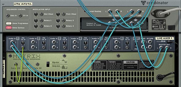
The last way I’m going to discuss is how you can use a Matrix to create your own waveform to affect the panning of a sound source. This is just like the previous methods, except you draw in a pattern inside the matrix, and on the back you connect the Curve CV to the Pan CV input on the first channel of the line mixer. Be sure to change the front panel of the matrix to “Curve” and on the back, select “Bipolar” as the curve selection. Panning is a bipolar process going from -64 to +63 with zero (0) being dead center. So the matrix needs to utilize this bipolar functionality to have the panning work correctly.

The Matrix Curve CV being sent to the Pan CV input on channel 1 of the mixer
The Matrix Curve CV being sent to the Pan CV input on channel 1 of the mixer The Matrix from the front with a Curve setup.

The drawback is that the curves are always in sync with the tempo (which may or may not be what you want), and your rate selection is limited to locked-in resolutions in the matrix. You can’t have any concept of a free-running rate system with this setup. On the plus side, you can draw in up to 32 unique patterns (on each of the matrix pattern banks), and then assign a rotary to the pattern selection to cycle through the different programmed curve patterns.

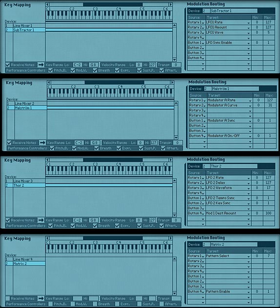
Now, I’ll show you how the Modulation Matrix is set up on each of the Combinators. Looking at these setups, you can see how each one has a different set of parameters that can be controlled. This is how you determine what the right “fit” is for your sound source. Get to know these inside out and it will become really easy to figure out which one works best for each of your audio scenarios:

From top to bottom: Sub, Mal, Thor, Matrix auto-panner Combinator setups.

So there you have it. A few different ways you can auto-pan your sound source. Things can get pretty interesting if you start crossing pans or inverting one sound source with another, so that when one sound is in the left channel, another sound is in the right channel (hint: use the spider’s “inverted” split to output one CV split to the second channel). You also don’t have to use an LFO to achieve your panning. You can easily draw in automation for the panning knob on the mixer channels and have full control over drawing in the panning curves yourself in the sequencer. Oh there’s lots of possibilities.

So do you have any suggestions or other interesting ways you’ve developed for panning your elements in Reason and Record. I’m always looking for innovative ways to use panning in my mixes. It’s a great way to add some movement and modulation to your pieces. Move up the rate fast enough and you almost have a vibrato or phased effect on your sound, which can add interest. So tell me what you’ve come up with and share it with all of us.

Here’s a bonus little rns file for Sterioevo (see his comment below). He was suggesting using an RPG-8 as a Panning device. Now the problem with this is that the Arp is not bipolar. The notes / gate CV output from the Arp is unipolar. So with a little tweaking, you can create something that comes close. A kind of pseudo-panner using the Arp. This was a pretty interesting technique so I thought I would provide the file here: arp-auto-panner-idea Enjoy!

Selig also had a comment on the Propellerhead forum that is important when talking about panning your audio. I thought I would quote him here, as it’s a very good point:

“The main problem I always had with using the CV Pan input is that the panning only goes half way to either side – I want a panner that goes ALL THE WAY!!! And the easy way to accomplish that is to route the LFO’s CV output (from any synth) to a combinator Rotary Knob’s rear input (cranking the little knob up all the way) and assign it to the mixer’s Panner with the combi’s Programmer. Check it out – NOW you have some serious P – A – N – N – I – N – G ! And all your cool tips will still apply. :-)”