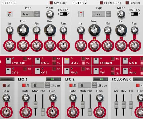
 In my fervent attempt to learn every single Rack Extension in the known universe, I stumbled upon Etch Red. And then I started creating, and just kept going and going and going. You see, this is part of the fun of the Rack Extensions. I’m starting to learn it’s not always about pitting the default Reason software against a particular Rack Extension. It’s just as important that a Rack Extension motivates you to create more. To that end, Etch Red was a seriously fun creative tool that allowed me to experiment on a large scale. So I thought I would share some of these experimentations with you.
You can download the patches here: Etch Red Patch Pack. There are 20 patches included: 8 Combinators (4 Instruments and 4 Effect devices), along with 12 Etch Red device patches. In order to use them, you will need Reason 6.5+ and the Etch Red Rack Extension.
I hope you enjoy the patches. And if you do, please consider donating here: [paypal-donation]
Now a little bit about the patch pack. There are two sections:
- Combinators — There are 4 instrument patches and 4 effect devices, all of which make use of Etch Red.
- Etch Red Device Patches — Since Etch Red can save it’s own patches, I’ve included 12 .repatch files as well.
Here is a brief description of each patch you’ll find inside this pack:
FX Combinators
-
Drive LP FX.cmb
This patch Combines the various drive modes of Etch Red and pairs them with a Low Pass Filter. Use Rotary 1 for the Drive amount, and Rotary 2 to switch between the seven drive modes. Rotary 3 and 4 allow you to shape the LP filter (Frequency and Resonance). You can turn the drive or filter on or off using the first two buttons. And even apply some Drive modulation using button 3. Lastly, you can Pan the Filter using button 4.
-
Dual Auto-Panner FX.cmb
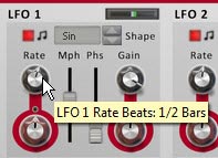
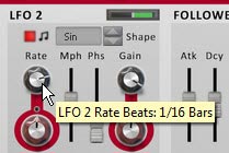
As it says in the name, this Combinator offers up some dual panning. It uses the two Etch Red LFOs in order to Pan the audio signal. In this way, you can create complex panning effects. The Rotaries control the depth (gain) and Rate of both Pans. You can also change between two different wave types (square and sine) for both Pans using Button 1 and 2. And if you like, you can turn off the second pan altogether using Button 3. Lastly, you can sync or un-sync Pan 1.
-
Hi – Lo Filter Splits (BP).cmb
This Combinator splits out the audio signal into the High and Low Frequencies. The fun comes in the fact that you can apply a different Bandpass filter to these two different Frequency splits independently. Use Rotary 1 to determine the crossover frequency, and then use Rotary 2 and 3 to set the Frequency for the High and Low Bandpass filters. There’s also a few other modulations and a HP filter that you can apply to both the High and Low Frequency streams, as well as some FM application if you like (on Rotary 4).
-
Tremolo & Vibrato FX.cmb
Tremolo affects the level of the audio signal (volume wobble), and Vibrato affects the Filter variance (Filter wobble). Using the Combinator Rotaries and buttons, you can control both in a variety of ways. You can adjust their Level, Rate, and what wave shape is used for the wobbling.
Instrument Combinators
-
Dubstep Bass C.cmb
As the name suggests, this is a Dubstep Bass experiment. You can adjust Filter Frequency, Drive, FM, and Wobble Glide using the rotaries, as well as some other adjustments using the buttons. Hint: If you don’t like the wobble pattern, open up the Combinator, and change the Thor step sequencer Velocity and Step Count. The velocity controls the Rate of the LFO in Etch Red, and therefore the type of Wobble you hear.
-
Easy Etch Synth Pad Hybrid.cmb
This is a nice hybrid between a polyphonic synth and pad instrument. Use Rotary 3 to smoothly transition between a Synth (fully left) and a Pad (fully right). Frequency and Resonance are on Rotaries 1 & 2. And you can control the level of the Sub Oscillator on Rotary 3. Button 1 and Button 2 control various Modulations applied to the Filter Frequency and FM, respectively. And try out the Pad Wrapper on button 3, which adds a nice shaper modulation to the sound.
-
Hooveretch.cmb
Where Etch Red meets a Hoover style sound. There’s even a Thor Step Sequencer thrown in for an Arpeggiated rhythm. Probably one of my favorite sounds of the bunch. You can control the Filter Frequencies using the first two Rotaries, and the level of the Sub Oscillator on Rotary 3. You can also use Rotary 4 to detune the main two Oscillators. Add in some Delay, FM, and Shaper, and you have yourself a really nice rich Bass.
-
Memory Pad
Another Pad, I think this one has a nice upbeat sound, yet still floats in the background. It’s more Rhythmic in nature, but you can dampen that if you like by turning down the “Flicker” rotary (Rotary 3) and turning switching to the alternate Wave type (Turn button 1 On).
Etch Red Device Patches
-
Basic Auto-Panner.repatch
The name is pretty self-explanatory. This is a patch that allows you to pan any audio signal.
-
Comb Phreak.repatch
Difficult to explain. Baiscally uses a Comb along with some drive to create a pretty wild little sound. Great for a sci-fi effect.
-
Deep Basso.repatch
Try this one out on your Bass sounds. It tends to raise the level and spreads out the Bass sound a little for you.
-
Dueling Filter Sweeps.repatch
This one is a double-sweep using two slow LFOs. Try to use this on a sound with a long ADSR time, like a Pad. That way you really get a chance to hear the sweep.
-
Ghost Pad.repatch
This is one of my favorites, and is great for smooth Pads and textures. It creates almost a feedback echo on your sound, but it’s a slow sweeping echo. So give it some musical room to breathe. Long held notes for this one.
-
Grunge Guitar.repatch
How could I do an Etch Red Patch Pack without a great distorted effect for Guitar. Nuff said.
-
Kick Variable Enhancer.repatch
Use this on your Kicks. It adds both punch and enough variation in the Filtering / Resonance so that it doesn’t become static. Instead your Kick drum will display a little variation each time it’s played.
-
LFO Grind Drive Distort.repatch
Another wacky and heavily distorted sound. There’s a lot of vibration and drive in this one. Try it with a bass or synth sound. Or even a texture or drone sound.
-
Simple Tremolo.repatch
This is a simplified version of Tremolo, and shows you how you can wobble the level of any audio source.
-
Panned Combs.repatch
A very simple patch that takes the audio coming into Etch Red and sends it through two Comb filters in parallel. Then the signal is panned left and right.
-
Snare Variable Dual Filter.repatch
Like the Kick Variable patch, except this one was built for snares.
-
Whacky Comb.repatch
Something a little more “out there” using a Comb filter. Try it out for some weird glitchiness.
So that’s what you’ll find included in the free Etch Red Patch Pack. Let me know what you think. Now I have to go wrap my head around Peff’s excellent Directre Rack Extension. Deep! Until next time, I hope some of what I do inspires you. All my best.